
Instructions

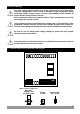


Table Of Contents
- Page 1
- Page 2
- Page 3
- Page 4
- Page 5
- Page 6
- Page 7
- Page 8
- Page 9
- Page 10
- Page 11
- Page 12
- Page 13
- Page 14
- Page 15
- Page 16
- Page 17
- Page 18
- Page 19
- Page 20
- Page 21
- Page 22
- Page 23
- Page 24
- Page 25
- Page 26
- Page 27
- Page 28
- Page 29
- Page 30
- Page 31
- Page 32
- Page 33
- Page 34
- Page 35
- Page 36
- Page 37
- Page 38
- Page 39
- Page 40
- Page 41
- Page 42
- Page 43
- Page 44
- Page 45
- Page 46

3.6.1 TC (Thermocouple) Connection
3.6 Temperature Input Connection
3.6.2 RTD Connections
Note 1 : In 3-wire system, use always cables of the same diameter (min 1mm²)
Its necessary to use cable in the same gauge and type for doing the line compensation
properly.
Note 2 : Install a jumper between terminals 2 and 3 when using a 2-wire RTD.
Note 3 : If the distance is longer than 10 meters, use 3-wire system.
3-wire PT-100 connection
(with line compensation)
(Max. Line impedance is 10 W)
2-wire PT-100 connection
(without line compensation)
Input resistance is greater than 10 M W.
ii
1 12 23 3
PT-100
Note 1
Note 2
PT-100
17
1 2
TC
Connect the wires with the polarity as shown in the figure at left.
Always use compensation wire corresponding to
the thermocouple used. If present, the shield must
be connected to a proper ground.
ii
Input resistance is greater than 10 M W.
ii
3
3.6.3 PTC and NTC Connections
Input resistance is greater than 10 M W.r.
ii
While doing the PTC Probe connection, pay attention to the PTC Probe cable
colour.
ii
RED
1 2
PTC
WHITE
1 2
NTC