
Instructions

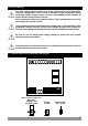


Table Of Contents
- Page 1
- Page 2
- Page 3
- Page 4
- Page 5
- Page 6
- Page 7
- Page 8
- Page 9
- Page 10
- Page 11
- Page 12
- Page 13
- Page 14
- Page 15
- Page 16
- Page 17
- Page 18
- Page 19
- Page 20
- Page 21
- Page 22
- Page 23
- Page 24
- Page 25
- Page 26
- Page 27
- Page 28
- Page 29
- Page 30
- Page 31
- Page 32
- Page 33
- Page 34
- Page 35
- Page 36
- Page 37
- Page 38
- Page 39
- Page 40
- Page 41
- Page 42
- Page 43
- Page 44
- Page 45
- Page 46

3.2 Electrical Wiring Diagram
Electrical wiring of the device must be the same as ‘Electrical Wiring Diagram’
below to prevent damage to the process being controlled and personnel
injury.
c
Temperature input is in CAT II class.
ii
13
Temperature Input
10
aa
CAT II
P/N : ESM-9910
Y
c
1 2 3 11
(TC, PT-100, PTC or NTC)
Relay Output
This Relay Module is in
ESM-9910.A.BC.0.1/01.00
types
Relay Output
This Relay Module is in
ESM-9910.A.BC.0.1/01.00 and
ESM-9910.A.BC.0.1/00.00
types
C
7A@250VV
OUTPUT-1
NCNOC
7A@250VV
OUTPUT-2
NCNO
4 5 6 7 8 9
TC
+
ı
PTC, NTC
PT 100
Supply Voltage Input
230 V V (±%15) 50/60 Hz - 3 VA
115 V V (±%15) 50/60 Hz - 3 VA
24 V V (±%15) 50/60 Hz - 3 VA
24 V W ( - %15, + %10 ) 50/60 Hz - 3 VA
(It must be determined in order)
L
(+)
N
(-)