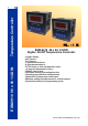
Temperature Controller ESM-9910 96 x 96 1/4 DIN ESM-9910 96 x 96 1/4 DIN Digital, On/Off Temperature Controller - 3 Digits display - NTC Input or, PTC Input or, J type thermocouple or, K type thermocouple or, PT-100 2-wire or 3-wire temperature input ( It must be determined in order ) - ON/OFF control form - Selectable heating and cooling function - Operating type selection with hysteresis - Adjustment of temperature offset value - Minimum pulling time adjustment for control outputs - Password protection f
ABOUT INSTRUCTION MANUAL Instruction manual of ESM-9910 temperature controller consists of three main sections. Explanation of these sections are below. Also, there are other sections which include order information and technical specifications of the device. All titles and page numbers in instruction manual are in “CONTENTS” section. User can reach to any title with section number. Installation: In this section, physical dimensions of the device, panel mounting, electrical wiring are explained.
CONTENTS 1.PREFACE............................................................................................................................................ Page 1.1 GENERAL SPECIFICATIONS 1.2 ORDERING INFORMATION 1.3 WARRANTY 1.4 MAINTENANCE 5 2.INSTALLATION.................................................................................................................................... Page 2.1 GENERAL DESCRIPTION 2.2 FRONT VIEW AND DIMENSIONS OF ESM-9910 TEMPERATURE CONTROLLER WITH ONE RELAY 2.
EU DECLARATION OF CONFORMITY Manufacturer’s Name : EMKO ELEKTRONIK A.S. Manufacturer’s Address : DOSAB, Karanfil Sk.
1.Preface ESM series temperature controllers are designed for measuring and controlling temperature. They can be used in many applications with On/Off control form and heating and cooling selection. Some application fields which they are used are listed below: Application Fields Glass Plastic Petro-Chemistry Textile Automative Machine Production Industries 1.
1.2 Ordering Information ESM-9910 (96x96 1/4 DIN ) A BC D 0 E / FG HI / U / 00 / 2 V W Z 0 0 A Supply Voltage 2 24 V W ( - %15, + %10 ) 50/60 Hz 3 24 V V ( ± %15 ) 50/60 Hz 4 115 V V ( ± %15 ) 50/60 Hz 5 230 V V ( ± %15 ) 50/60 Hz 9 Customer BC 12 15 09 03 05 10 18 19 Input Type PTC (Note-1) PTC (Note-1) PT 100 , IEC751(ITS90) PT 100 , IEC751(ITS90) J ,Fe CuNi IEC584.1(ITS90) K ,NiCr Ni IEC584.1(ITS90) NTC (Note-1) NTC (Note-1) Scale(°C) 150°C -50°C -19.9°C 99.9°C -19.9°C 99.
2.Installation c Before beginning installation of this product, please read the instruction manual and warnings below carefully. In package , - One piece unit - Two pieces mounting clamps - One piece instruction manual A visual inspection of this product for possible damage occured during shipment is recommended before installation. It is your responsibility to ensure that qualified mechanical and electrical technicians install this product.
2.1 General Description ESM -99 Mounting Clamp 10 Front Panel IP65 protection NEMA 4X Panel surface (maximum thickness 15 mm / 0.59 inch) 2.2 Front View and Dimensions of ESM-9910 Temperature Controller with One Relay OUT 96 mm / 3.78 inch Maximum 15 mm / 0.59 inch PROG SET SET P ESM-9910 96 mm / 3.78 inch 12 ± 1 mm / 0.47 inch 84 mm / 3.
2.3 Front View and Dimensions of ESM-9910 Temperature Controller with Two Relays 96 mm / 3.78 inch Maximum 15 mm / 0.59 inch ESM-9910 96 mm / 3.78 inch 12 ± 1 mm / 0.47 inch 84 mm / 3.31 inch 2.4 Panel Cut-Out 92 mm / 3.62 inch 129 mm/5,08 inch (min) 129 mm/5,08 inch (min) 92 mm / 3.
2.5 Environmental Ratings Operating Conditions Operating Temperature : 0 to 50 °C Max. Operating Humidity : 90% Rh (non-condensing) Altitude c : Up to 2000 m. Forbidden Conditions: Corrosive atmosphere Explosive atmosphere Home applications (The unit is only for industrial applications) 2.6 Panel Mounting 1 1-Before mounting the device in your panel, make sure that the cut-out is of the right size. 2-Check front panel gasket position 3-Insert the device through the cutout.
2.7 Installation Fixing Clamp 1 2 The unit is designed for panel mounting. 1-Insert the unit in the panel cut-out from the front side. 2- Insert the mounting clamps to the holes that located top and screw up the fixing screws until the unit completely immobile within the panel ESM -9 c 910 Montage of the unit to a system must be done with it’s own fixing clamps. Do not do the montage of the device with inappropriate fixing clamps. Be sure that device will not fall while doing the montage. 2.
3.Electrical Wirings c c c c You must ensure that the device is correctly configured for your application. Incorrect configuration could result in damage to the temperature being controlled, and/or personal injury. It is your responsibility, as the installer, to ensure that the configuration is correct. Device parameters has factory default values. These parameters must be set according to the system’s needs. Only qualified personnel and technicians should work on this equipment.
3.2 Electrical Wiring Diagram c Electrical wiring of the device must be the same as ‘Electrical Wiring Diagram’ below to prevent damage to the process being controlled and personnel injury. P/N : ESM-9910 c Y CAT II PTC, NTC + TC ı PT 100 1 2 3 OUTPUT-2 7A@250VV C OUTPUT-1 7A@250VV NO NC C NO NC 4 5 6 7 8 9 10 11 a L N (+) (-) Temperature Input (TC, PT-100, PTC or NTC) Relay Output This Relay Module is in ESM-9910.A.BC.0.1/01.
3.3 Labels for ESM-9910 Temperature Controller with One Relay Rear label appearance of the device that have PT-100 (-19.9oC ; + 99.9oC) Scale Rear label appearance of the device that have PT-100 (0oC ; 400oC) Scale c a Y CAT II P/N : ESM - 9910 - 5.09.0.1/00.00/2.0.0.0 P/N : ESM - 9910 - 5.03.0.1/00.00/2.0.0.0 m m Pt-100 (-19.9 ; +99.
3.4 Labels for ESM-9910 Temperature Controller with Two Relays Rear label appearance of the device that have PT-100 (-19.9oC ; + 99.9oC) Scale Rear label appearance of the device that have PT-100 (0oC ; 400oC) Scale c a Y CAT II P/N : ESM - 9910 - 5.09.0.1/01.00/2.0.0.0 P/N : ESM - 9910 - 5.03.0.1/01.00/2.0.0.0 m m Pt-100 (-19.9 ; +99.
3.
3.6 Temperature Input Connection 3.6.1 TC (Thermocouple) Connection TC 1 Connect the wires with the polarity as shown in the figure at left. i Always use compensation wire corresponding to the thermocouple used. If present, the shield must be connected to a proper ground. i Input resistance is greater than 10 M W. 3 2 3.6.2 RTD Connections PT-100 PT-100 Note 2 Note 1 1 2 3 1 2 3 2-wire PT-100 connection 3-wire PT-100 connection (without line compensation) (with line compensation) (Max.
3.7 Galvanic Isolation Test Values of ESM-9910 Temperature Controller 2000V V ( For ESM-9910.5...,ESM-9910.4.... ) 500V V ( For ESM-9910.3....,ESM-9910.2.... ) Supply Input 10 Ground 11 2000V V Output-1 Relay Output 2000V V Output-2 Relay Output 2000V V Analogue Inputs 2 2000V V 7 8 9 2000V V 4 5 6 1 3 3.8 Output-1 Connection 3.8.
3.8.2 SSR Driver Output-1 Connection Device 7 L N Last Control Element (SSR) 8 Max.15 V Z Max.
3.9 Output-2 Connections 3.9.1 Output-2 (Relay Output) Connection L N Device C 4 NC 6 7A V T Fuse Last Control Element (Contactor) NO 5 c Fuse c i Load Fuses must be selected according to the application Output-2 exists in device with two relays 3.9.2 SSR Driver Output-2 Connection Device Last Control Element L N (SSR) 4 5 Max.15 V Z Max.
4. Front Panel Definition and Accessing to the Menus 4.
4.
4.3 Observation of ESM-9910 Temperature Controller Software Revision When power is applied to the device, software revision number is momentarily shown on the display. “ r”Þ Revision Software Revision number ESM-9910 ESM-9910 Main operation screen is shown c If there is an unexpected situation while opening the device, power off the device and inform a qualified personnel.
4.4 Changing and Saving Set Values 4.4.1 ESM-9910 with One Relay When SET button is pressed, SET led lights on and SET value is seen on display. Main Operation Screen OUT PROG SET SET SET Value Screen OUT PROG SET SET SET value can be changed with increment and decrement buttons. SET Value Screen OUT PROG SET Press SET button again to exit without saving SET value. Press Enter button for saving SET value.
4.4.2 ESM-9910 with Two Relays Adjustment of SET1 value Main Operation Screen When SET1 button is pressed, SET1 led lights on and SET1 value is seen on display. SET1 Value Screen SET1 value can be changed with increment and decrement buttons. SET1 Value Screen Press SET1 button again to exit without saving SET1 value. Main Operation Screen i Press SET2/Enter button for saving SET1 value. For both conditions SET1 led lights off and it turns to main operation screen.
Adjustment of SET2 value Main Operation Screen When SET2 button is pressed, SET2 led lights on and SET2 value is seen on display. SET2 Value Screen SET2 value can be changed with increment and decrement buttons. SET2 Value Screen Press SET1 button to exit without saving SET2 value. Main Operation Screen i Press SET2/Enter button for saving SET2 value. For both conditions, SET2 led lights off and it turns to main operation screen.
4.5 Entering to Programming Mode, Changing and Saving Parameters 4.5.1 ESM-9910 with One Relay Main Operation Screen When SET button is pressed for 10 seconds, “PROG” led starts to blink.
Hysteresis Parameter Parameter value can be observed by pressing increment button. Programming Screen In programming screen, Press SET1 button to exit from programming mode and turn to the main operation screen. OUT PROG SET If Enter button is pressed next parameter is shown. SET Hysteresis Value OUT In programming screen, Press SET button to exit from programming mode and turn to the main operation screen. If Enter button is pressed next parameter is shown.
Operation Type Selection for Output Parameter value can be observed by pressing increment button. Programming Screen In programming screen, Press SET1 button to exit from programming mode and turn to the main operation screen. OUT PROG SET OUT In programming screen, Press SET button to exit from programming mode and turn to the main operation screen. If Enter button is pressed next parameter is shown.
Process Offset Parameter Programming Screen In programming screen, Press SET1 button to exit from programming mode and turn to the main operation screen. OUT Parameter value can be observed by pressing increment button. PROG SET If Enter button is pressed, next parameter is shown. SET Process Offset Value OUT Press SET button to turn to the programming screen without saving the parameter. If Enter button is pressed, next parameter is shown.
Minimum Pulling Time for Output Parameter Programming Screen In programming screen, Press SET1 button to exit from programming mode and turn to the main operation screen. OUT Parameter value can be observed by pressing increment button. PROG SET If Enter button is pressed, next parameter is shown. SET Value of Minimum Pulling Time for Output OUT Press SET button to turn to the programming screen without saving the parameter. If Enter button is pressed, next parameter is shown.
Programming Mode Accessing Password Programming Screen In programming screen, Press SET1 button to exit from programming mode and turn to the main operation screen. OUT Parameter value can be observed by pressing increment button. PROG SET If Enter button is pressed, next parameter is shown. SET Programming Mode Accessing Password Value OUT Press SET button to turn to the programming screen without saving the parameter. If Enter button is pressed, next parameter is shown.
4.5.2 ESM-9910 with Two Relays Main Operation Screen When SET1 button is pressed for 10 seconds, “PROG” led starts to blink.
Hysteresis-1 Parameter Programming Screen Parameter value can be observed by pressing increment button. In programming screen, Press SET1 button to exit from programming mode and turn to the main operation screen. If SET2/Enter button is pressed, next parameter is shown. Hysteresis-1 Value If SET2/Enter button is pressed, next parameter is shown. Parameter can be changed with increment and decrement buttons. Press SET1 button to exit without saving parameter value.
Hysteresis-2 Parameter Programming Screen Parameter value can be observed by pressing increment button. In programming screen, Press SET1 button to exit from programming mode and turn to the main operation screen. If SET2/Enter button is pressed, next parameter is shown. Hysteresis-2 Value If SET2/Enter button is pressed, next parameter is shown. Parameter can be changed with increment and decrement buttons. Press SET1 button to exit without saving parameter value.
Operation Type Selection for Output-1 Programming Screen Parameter value can be observed by pressing increment button. In programming screen, Press SET1 button to exit from programming mode and turn to the main operation screen. If SET2/Enter button is pressed, next parameter is shown. Value of Operation Type Selection for Output-1 Heating is selected If SET2/Enter button is pressed, next parameter is shown.
Operation Type Selection for Output-2 Programming Screen Parameter value can be observed by pressing increment button. In programming screen, Press SET1 button to exit from programming mode and turn to the main operation screen. If SET2/Enter button is pressed, next parameter is shown. Value of Operation Type Selection for Output-2 Heating is selected If SET2/Enter button is pressed, next parameter is shown. Parameter can be changed with increment and decrement buttons.
Process Offset Parameter Programming Screen Parameter value can be observed by pressing increment button. In programming screen, Press SET1 button to exit from programming mode and turn to the main operation screen. If SET2/Enter button is pressed, next parameter is shown. Process Offset Value If SET2/Enter button is pressed, next parameter is shown. Press SET1 button to turn to the programming screen without saving the parameter. Parameter can be changed with increment and decrement buttons.
Minimum Pulling Time for Output-1 Programming Screen Parameter value can be observed by pressing increment button. In programming screen, Press SET1 button to exit from programming mode and turn to the main operation screen. If SET2/Enter button is pressed, next parameter is shown. Value of Minimum Pulling Time for Output-1 If SET2/Enter button is pressed, next parameter is shown. Press SET1 button to turn to the programming screen without saving the parameter.
Minimum Pulling Time for Output-1 Programming Screen Parameter value can be observed by pressing increment button. In programming screen, Press SET1 button to exit from programming mode and turn to the main operation screen. If SET2/Enter button is pressed, next parameter is shown. Value of Minimum Pulling Time for Output-1 If SET2/Enter button is pressed, next parameter is shown. Press SET1 button to turn to the programming screen without saving the parameter.
5. Parameters Parameters are divided into two groups as SET and PROGRAM parameters. 5.1 Set Parameters SET1 SET value for Output-1. Control of output-1 relay is done according to this value. This value can be adjusted according to input type, minimum and maximum of scale. SET2 SET value for Output-2. Control of output-2 relay is done according to this value. This value can be adjusted according to input type, minimum and maximum of scale. THIS PARAMETER IS NOT ACTIVE IN DEVICES WITH ONE RELAY. 5.
Operation type selection parameter of output-2. THIS PARAMETER IS NOT ACTIVE IN DEVICES WITH ONE RELAY. Operation Type of Output-2 relay can be adjusted as “HEATING”. Normally energised. Operation Type of Output-2 relay can be adjusted as “COOLING”. Normally de-energised. Process Offset Parameter (Default = 0). This parameter is offset for the process value. This defined value is added to the process value. -10 to 10 °C for TC Type Devices, -10 to 10 °C for PT-100 (0°C , 400°C), -10.0 to 10.
6. Failure Messages in ESM-9910 Temperature Controllers Sensor failure in analogue inputs. It means sensor connection is wrong or there is no sensor.
7. Control Algorithm 7.1 ON/OFF Control In ON/OFF control algorithm, temperature value is tried to keep equal to set value by opening or closing the last control element. ON/OFF controlled system, temperature value oscillates continuously. Temperature value’s oscillation period or amplitude around set value changes according to controlled system. For reducing oscillation period of temperature value, a threshold zone is formed below or around set value and this zone is named hysteresis.
8. Specifications Device Type Housing&Mounting : Temperature Controller : 96 mm x 96 mm x 96 mm 1/4 DIN 43700 plastic housing for panel mounting. Panel cut-out is 92 x 92 mm Type-1 Enclosure Mounting Protection Class : NEMA 4X (IP65 at front, IP20 at rear) Weight : Approximately 0.28 Kg. Environmental Ratings : Standard, indoor at an altitude of less then 2000 meters with non-condensing humidity. Storage/Operating Temperature : -40 oC to +85 oC / 0 oC to +50 oC Storage/Operating Humidity : 90 % max.
9. Other Informations Manufacturer Information: Emko Elektronik Sanayi ve Ticaret A.Ş. Demirtaş Organize Sanayi Bölgesi Karanfil Sk. No:6 16369 BURSA/TURKEY Phone : +90 224 261 1900 Fax : +90 224 261 1912 Repair and Maintenance Service Information: Emko Elektronik Sanayi ve Ticaret A.Ş. Demirtaş Organize Sanayi Bölgesi Karanfil Sk. No:6 16369 BURSA/TURKEY Phone : +90 224 261 1900 Fax : +90 224 261 1912 Thank you very much for your preference to use Emko Elektronik Your Technology Partner Products. www.