
Instructions
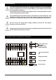
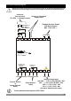
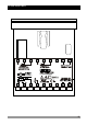
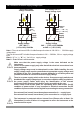
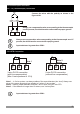
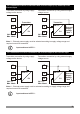
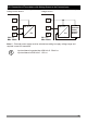
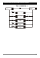
Table Of Contents
- Page 1
- Page 2
- Page 3
- Page 4
- Page 5
- Page 6
- Page 7
- Page 8
- Page 9
- Page 10
- Page 11
- Page 12
- Page 13
- Page 14
- Page 15
- Page 16
- Page 17
- Page 18
- Page 19
- Page 20
- Page 21
- Page 22
- Page 23
- Page 24
- Page 25
- Page 26
- Page 27
- Page 28
- Page 29
- Page 30
- Page 31
- Page 32
- Page 33
- Page 34
- Page 35
- Page 36
- Page 37
- Page 38
- Page 39
- Page 40
- Page 41
- Page 42
- Page 43
- Page 44
- Page 45
- Page 46
- Page 47
- Page 48
- Page 49
- Page 50
- Page 51
- Page 52
- Page 53
- Page 54
- Page 55
- Page 56
- Page 57
- Page 58
- Page 59
- Page 60
- Page 61
- Page 62
- Page 63
- Page 64
- Page 65
- Page 66

14
Sensor or Transmitter
Supply Input
24 V Z
Max 50mA
TC
Pt-100
0 to 50mV Z
0 to 10V Z
0 to 20mA Z
Universal
Process Input
(TC, RTD, Z Voltage/Current)
Standard Process Output
SSR Driver Output
Process Output
or
Alarm Output-2
Relay
Alarm Output-1
Relay
1
10
2
11
3
12
4
13
5
14
6
15
CAT II
P/N : ESM-7730
Y
c
7
8 9
16 17 18
a
Process Out
Max. 17mA, 25V Z
Process measurement input is in CAT II class.
ii
Supply Voltage Input
100-240V V (-15%;+10%) 50/60Hz - 6VA
24 V V (-15%;+10%) 50/60Hz - 6VA
24V Z (-15%;+10%) - 6W
12V Z (-15%;+10%) - 6W
(It must be determined in order)
ALARM OUT-1
5A@250VV
NO CNC
(ALARM OUT-2)
PROCESS OUT
5A@250VV
NO CNC
3.2 Electrical Wiring Diagram
Electrical wiring of the device must be the same as ‘Electrical Wiring Diagram’
below to prevent damage to the process being controlled and personnel injury.
c