
Instructions
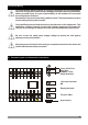
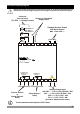
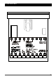
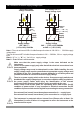
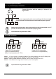
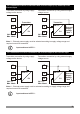
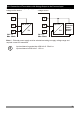
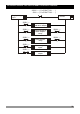
Table Of Contents
- Page 1
- Page 2
- Page 3
- Page 4
- Page 5
- Page 6
- Page 7
- Page 8
- Page 9
- Page 10
- Page 11
- Page 12
- Page 13
- Page 14
- Page 15
- Page 16
- Page 17
- Page 18
- Page 19
- Page 20
- Page 21
- Page 22
- Page 23
- Page 24
- Page 25
- Page 26
- Page 27
- Page 28
- Page 29
- Page 30
- Page 31
- Page 32
- Page 33
- Page 34
- Page 35
- Page 36
- Page 37
- Page 38
- Page 39
- Page 40
- Page 41
- Page 42
- Page 43
- Page 44
- Page 45
- Page 46
- Page 47
- Page 48
- Page 49
- Page 50
- Page 51
- Page 52
- Page 53
- Page 54
- Page 55
- Page 56
- Page 57
- Page 58
- Page 59
- Page 60
- Page 61
- Page 62
- Page 63
- Page 64
- Page 65
- Page 66

13
1
10
2
11
3
12
4
13
5
14
6
15
7
16
8
17
9
18
0,5Nm
aa
6 mm / 0.236 inch
Wire Size:
18 AWG / 1 mm²
Solid /Stranded
18 screws terminal
M3
Empty terminals
Torque 0.5 Nm
Screw driver
You must ensure that the device is correctly configured for your application.
Incorrect configuration could result in damage to the process being controlled,
and/or personal injury. It is your responsibility, as the installer, to ensure that
the configuration is correct.
Parameters of the device has factory default values. These parameters must be
set according to the system’s needs.
Only qualified personnel and technicians should work on this equipment. This
equipment contains internal circuits with voltage dangerous to human life.
There is severe danger for human life in the case of unauthorized intervention.
Be sure to use the rated power supply voltage to protect the unit against
damage and to prevent failure.
Keep the power off until all of the wiring is completed so that electric shock and
trouble with the unit can be prevented.
3.Electrical Wiring
c
c
c
c
3.1 Terminal Layout and Connection Instructions