
User manual


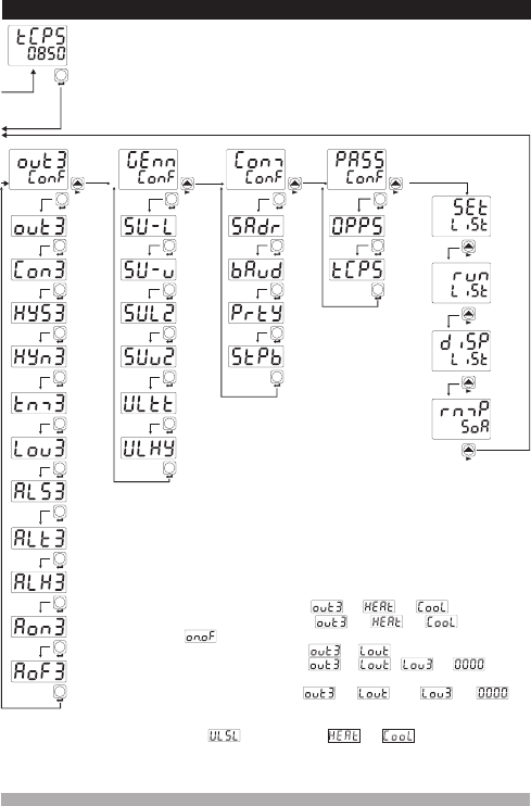
7.5 Easy Access Diagram for Technician Parameters
Out3
menu
47
°C
°F
V
O1
O2
O3
SV
REMOTE RAMP MAN AUTO
AT
SET
SET
SV
REMOTE
RAMP MAN AUTO
°C
°F
V
O1
O2
O3
AT
SET
Not-6
SET
Not-7
SET
Not-7
SET
Not-7
Not-8
SET
SET
Not-9
SET
Note-10
SET
SET
SET
SET
Genn
menu
SET
SV
REMOTE
RAMP MAN AUTO
°C
°F
V
O1
O2
O3
AT
SET
SET
Note-11
SET
SET
SET
SET
Comm
menu
Pass
menu
SET SET
SV
REMOTE
RAMP MAN AUTO
°C
°F
V
O1
O2
O3
AT
SV
REMOTE
RAMP MAN AUTO
°C
°F
V
O1
O2
O3
AT
SET SET
Note-13
SET SET
SET
SET
SV
REMOTE
RAMP MAN AUTO
°C
°F
V
O1
O2
O3
AT
SV
REMOTE
RAMP MAN AUTO
°C
°F
V
O1
O2
O3
AT
SV
REMOTE
RAMP MAN AUTO
°C
°F
V
O1
O2
O3
AT
SV
REMOTE
RAMP MAN AUTO
°C
°F
V
O1
O2
O3
AT
Set
menu
Run List
menu
Display
menu
Ramp/
Soak
menu
Technician
Password
Entering
Screen
Confirm the
password
with SET/OK
button
Note-10
Note-10
Note-10
Note-11
Note-12
Note-12
Output
Function
Selection
Control
Algorithm
Out3
Hysteresis
Value
Hysteresis
Operation
Type
Minimum
on-time
Out3
Logic
Output
Measurement
Input Selection
for Alarm Out3
Out3
Alarm
Type
Alarm3
Hysteresis
Value
Alarm3
On Delay
Time
Alarm3
Off
Delay
Time
Set scale
Low Limit
Set scale
Up Limit
2nd
Sensor
Set Scale
Low Limit
2nd
Sensor
Set Scale
Up Limit
Motorized
Valve
Travel
time
Motorized
Valve
Step
Slave
Address
Baud
Rate
Parity
selection
Stop bit
selection
Operator
Password
Technician
Password
Note-13
Note-13
Note-13
It turns to the
beginning of the
menu list
Operator menus are
entered.
Note-6: It can be observed if is or
Note-7: It can be observed if is or and control
type is
Note-8: It can be observed if is
Note-9:It can be observed if is , is and an
analog input module is plugged in Module-1 or Module-2 socket
Note-12: If parameter is or , then these
parameters can be observed.
Note-13: Please refer to the Section 7.4 Operator Parameters easy
access diagram
Note-10: It can observed if is and is
Note-11: It can be observed if one of the analog input module is
plugged in Module-1 or Module-2 socket.