
User manual


°C
°F
V
O1
O2
O3
SV
REMOTE RAMP MAN AUTO
AT
ESM-4450
SET
Process Controller
°C
°F
V
O1
O2
O3
SV
REMOTE RAMP MAN AUTO
AT
ESM-4450
SET
Process Controller
42
SSR Driver and Digital Output
Module (EMO-410 ,EMO-420)
SSR Driver and Digital Output
Module (EMO-410,EMO-420)
Relay Output
Module (EMO-400)
Relay Output
Module (EMO-400)
0/4...20mA Current Output
Module (EMO-430)
Z 0/4...20mA Current
Output Module (EMO-430)
Z
Analog Input Module
(EMI-410,EMI-430,EMI-440
or EMI-450)
Digital Input Module
(EMI-400)
Digital Input Module
(EMI-400)
There is no module in
Module-1 socket
There is no module in
Module-2 socket
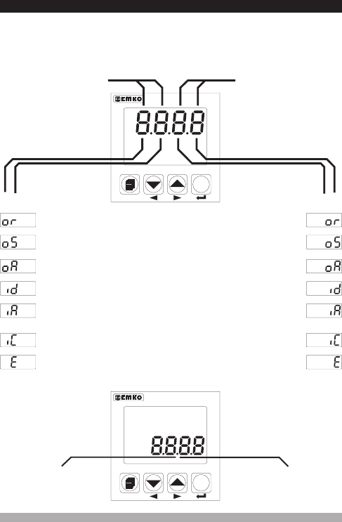
There are two sockets for plugging optional modules to the device. These modules are
recognized by the device automatically.
Module definiton codes and how to observe these codes of optional modules in
Module-1 and Module-2 socket are explained below :
When the power is applied to the device all led indicators
and display segments are momentarily illuminated for testing. Software revision number of the
controller on the bottom display and module definition codes on the top display are momentarily
illuminated.
Optional Input/Output
module code for Module-1
Optional Input/Output
module code for Module-2
7.2 Observation of Optional Modules and Software Revision on the Displays
“ rU” RevisionÞ
Revision number
Analog Input Module
(EMI-410,EMI-430,EMI-440
or EMI-450)
0...5 A CT Input
Module (EMI-420)
V 0...5 A CT Input
Module (EMI-420)
V