
User manual


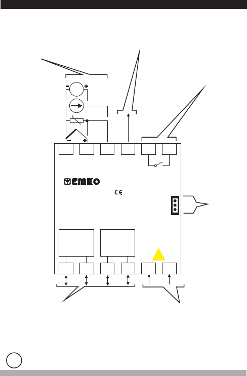
3.2 Electrical Wiring Diagram
Universal
Process Input
(TC, RTD, Voltage/Current)Z
Sensor or Transmitter
Supply Voltage
Output-3
Standard Relay Output
Supply Voltage Input
100-240V (- ) 50/60Hz
24 V (- 50/60Hz - 6VA
24V (-
(It must be determined in order)
V
V
Z
15%;+10%
15%;+10%)
15%;+10%) - 6W
-6VA
Electrical wiring of the device must be the same as ‘Electrical Wiring Diagram’
below to prevent damage to the process being controlled and personnel injury.
c
15
Optional Input/Output Module Terminals
Relay, SSR Driver, Digital or Current
Output Module
Digital, Analogue and CT
Input Modules
V
1
7
2
8
3
9
4
10
5
11
6
12
MODULE-1 MODULE-2
5A@250V V
OUTPUT - 3
12 V Z
Max 50mA
TC
Pt-100
0 to 20mA Z
0 to 50mV
0to10V
Z
Z
CAT II
P/N : ESM-4450
Y
a
c
Communication
Socket
C
NO
PTC , NTC
Process input, Analogue Module Inputs (EMI-410, EMI-430, EMI-440,EMI-450)
and are in CAT II class.VCT Module Input (EMI-420)
i