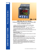
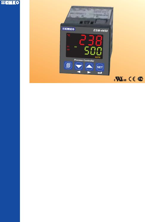
Process Controller ESM-4450 48x48 1/16 DIN ESM-4450 48 x 48 1/16 DIN Universal Input PID Process Controller with Smart I/O Module System - 4 digits process (PV) and 4 digits process set (SV) display - Universal process input (TC, RTD, mVZ , VZ , mAZ) - Optional secondary sensor input - Dual or multi point calibration for ZVoltage / Current input - Configurable ON/OFF, P, PI, PD and PID control forms - Adaptation of PID coefficients to the system with Auto-tune and Self-tune - Manual/Automatic mode selectio
ABOUT INSTRUCTION MANUAL Instruction manual of ESM-4450 Process Controller consists of two main sections. Explanation of these sections are below. Also, there are other sections which include order information and technical specifications of the device. All titles and page numbers in instruction manual are in “CONTENTS” section. User can reach to any title with section number.
CONTENTS 1.PREFACE............................................................................................................................................ Page 1.1 GENERAL SPECIFICATIONS 1.2 ORDERING INFORMATION 1.3 WARRANTY 1.4 MAINTENANCE 6 2.INSTALLATION....................................................................................................................................Page 2.1 GENERAL DESCRIPTION 2.2 DIMENSIONS 2.3 PANEL CUT-OUT 2.4 ENVIRONMENTAL RATINGS 2.5 PANEL MOUNTING 2.
5.1.7 CONNECTION OF EMI-440 PT-100 INPUT MODULE 5.1.8 CONNECTION OF EMI-450 0...10VZ INPUT MODULE 5.2 CONNECTION WIRINGS FOR OUTPUT MODULES 5.2.1 EMO-400 RELAY OUTPUT MODULE CONNECTION 5.2.2 EMO-410 SSR DRIVER MODULE CONNECTION 5.2.3 EMO-420 DIGITAL (TRANSISTOR) OUTPUT MODULE CONNECTION 5.2.4 EMO-430 0/4 ...20mAZ CURRENT OUTPUT MODULE CONNECTION 5.2.5 TO GET 0...10VZ WITH EMO-430 0/4 ...20mAZ CURRENT OUTPUT MODULE 6.CONNECTIONS FOR RS-232 / RS-485 SERIAL COMMUNICATION........................................
EU DECLARATION OF CONFORMITY Manufacturer Company Name : Emko Elektronik A.S. Manufacturer Company Address: DOSAB, Karanfil Sokak, No:6, 16369 Bursa, Turkiye The manufacturer hereby declares that the product conforms to the following standards and conditions.
1.Preface ESM series process controllers are designed for measuring and controlling temperature and any process value.They can be used in many applications with their universal process input, multifunction control outputs, selectable alarm functions, serial communication unit and input/output modules.
1.
1.3 Warranty EMKO Elektronik warrants that the equipment delivered is free from defects in material and workmanship. This warranty is provided for a period of two years. The warranty period starts from the delivery date. This warranty is in force if duty and responsibilities which are determined in warranty document and instruction manual performs by the customer completely. 1.4 Maintenance Repairs should only be performed by trained and specialized personnel.
2.Installation c Before beginning installation of this product, please read the instruction manual and warnings below carefully. In package , - One piece unit - Two piece mounting clamp - One piece instruction manual A visual inspection of this product for possible damage occured during shipment is recommended before installation. It is your responsibility to ensure that qualified mechanical and electrical technicians install this product.
2.1 General Description Mounting Clamp Terminal protection cover Product Label Front Panel IP65 protection NEMA 4X Panel surface (maximum thickness 5mm / 0.2 inch) 2.2 Dimensions °F V O1 AT SV O2 O3 REMOTE RAMP MAN AUTO Process Controller SET 48 mm / 1.89 inch ESM-4450 °C 48mm / 1.89 inch 11.5 ± 1 mm /0.45 inch 104.5 mm/ 4.
2.3 Panel Cut-Out 46 mm / 1.81 inch (min) 65 mm / 2.56 inch (min) 65 mm / 2.56 inch (min) 46 mm / 1.
2.4 Environmental Ratings Operating Conditions Operating Temperature : 0 to 50 °C Max. Operating Humidity : 90% Rh (non-condensing) Altitude c : Up to 2000m. Forbidden Conditions: Corrosive atmosphere Explosive atmosphere Home applications (The unit is only for industrial applications) 2.5 Panel Mounting 1 1-Before mounting the device in your panel, make sure that the cut-out is of the right size. 2-Check front panel gasket position 3-Insert the device through the cut-out.
2.6 Installation Fixing Clamp 2 1 The unit is designed for panel mounting. 1-Insert the unit in the panel cut-out from the front side. 2-Insert the mounting clamp from the rear side of the unit and screw up the fixing screws until the unit completely immobile within the panel c Montage of the unit to a system must be done with it’s own fixing clamps. Do not do the montage of the device with inappropriate fixing clamps. Be sure that device will not fall while doing the montage. 2.
3.Electrical Wirings c c c c You must ensure that the device is correctly configured for your application. Incorrect configuration could result in damage to the process being controlled, and/or personal injury. It is your responsibility, as the installer, to ensure that the configuration is correct. Device parameters has factory default values. These parameters must be set according to the system’s needs. Only qualified personnel and technicians should work on this equipment.
3.2 Electrical Wiring Diagram c Electrical wiring of the device must be the same as ‘Electrical Wiring Diagram’ below to prevent damage to the process being controlled and personnel injury.
3.
3.4 Process Input Connection 3.4.1 TC (Thermocouple) Connection Connect the wires with the polarity as shown in the figure left. TC 1 2 3 i Always use compensation wire corresponding to the thermocouple used. If present, the shield must be connected to a proper ground. i Input resistance is greater than 10M W. 3.4.2 RTD Connection Pt-100 Pt-100 Note 2 Note 1 1 2 3 3-wire Pt-100 connection (with line compensation) (Max.
3.4.3 Process Input Connection of Serial Transmitters with Current Output (Loop Powered) Transmitter connection by using supply voltage on the device 1 Transmitter connection by using external supply voltage source. 1 Transmitter 3 3 mAZ 4 Transmitter PV 12 VZ Max. 50mA mAZ 4 PV External Power Supply Note 1 12 VZ Max. 50mA Note 1 : External power supply must be selected according to supply voltage range and required current for transmitter. i Input Resistance is 2R7 W . 3.4.
3.4.5 Connection of Transmitters with Voltage Output to Process Input Transmitter connection by using supply voltage on the device Transmitter connection by using external supply voltage source. 1 1 mV, VZ 2 4 4 PV 12 VZ Max. 50mA Transmitter mV, VZ 2 PV 12 VZ Max. 50mA External Power Supply Note 1 Transmitter Note 1 : External power supply must be selected according to supply voltage range and required current for transmitter. i Input resistance is greater than 10M W for 0...
3.6 Galvanic Isolation Test Values of ESM-4450 Process Controller and Input/Output Modules Supply Voltage Input 2000V V ( For ESM-4450.1...... ) 500V V ( For ESM-4450.2...... ) 11 Ground 12 2000V V 5 2000V V 7 9 8 10 2000V V 7 9 8 10 2000V V 7 9 8 10 2000V V 7 9 8 10 2000V V 5 Output-3 Relay Output 6 EMO-400 Relay Output Module EMO-410 SSR Driver Output Module EMO-420 Digital Output Module EMO-430 0/4...
4.Definitions and Specifications of Modules ESM-4450 process controller is a modular product which is designed to operate with additional analogue and digital input/output units which user may need. Two input/output modules can be plugged in the device by the user. User may configure the product for different applications according to the system requirements with the input/output modules which are described in this section. 20.3mm 30.7mm 5mm Dimensions of Input/Output Modules 1.5mm 14mm 8.5mm 41.
4.1.2 EMI-410 0/4...20mAZ Current Input Module EMI-410 0/4...20mAZ current input module can be plugged in Module-1 or Module-2 socket to use as 2nd sensor input, for measuring process value or for using alarm functions which are related to measured value. Also,”remote set” function can be used by installing the module. Please refer to Section 8.2.3 or 8.2.
4.1.4 EMI-430 TC (Thermocouple) or 0...50mVZ Input Module EMI-430 TC or 0...50mVZ input module can be plugged in Module-1 or Module-2 socket to use as 2nd sensor input, for measuring process value or for using alarm functions which are related to measured value. Also “remote set” function can be used by plugging this module. Please refer to Section 8.2.3 or 8.2.4 for detailed information.
Applications of EMI-440 Pt-100 Input Module It can be used to measure any process value and use it with an alarm function in applications that 2nd sensor input is necessary. The Pt-100 value on the module input can be used as process set value when “remote set” function is activated and system can be controlled with analogue signal which is applied from remote point. i Detailed information about functions of EMI-440 Pt-100 input module are given in PARAMETERS section.
4.2 Output Modules 4.2.1 EMO-400 Relay Output Module EMO-400 Relay output module can be plugged in Module-1 or Module-2 socket to use functions which are defined for relay output. Specifications of EMO-400 Relay Output Module Output : 3A@250VV at resistive load, Single Open(or Close) Contact Dimensions : 14x30.7x41.4mm Electrical Life : 100.
4.2.3 EMO-420 Digital (Transistor) Output Module EMO-420 Digital (Transistor) Output Module can be plugged in Module-1 or Module-2 socket to use functions which are defined for digital output. Specifications of EMO-420 Digital (Transistor) Output Module Output : Maximum 40 mA, 15-18VZ ±10%, isolated Dimensions : 14x30.7x41.
4.3 Installing and Pulling Out Input/Output Modules c First, detach all cable connections from the device and uninstall it from the panel. Push to the lock pins where top and bottom of the device Pull the cover case with your other hand from front panel to rear side. Pull out the cover case from the device Slide input/output modules into socket. Pull out the module from it’s socket, instead of this module install the new one or other module user wants to use.
4.4 To Stick Input/Output Modules’ Labels to the Device Every module which is plugged in Module-1 or Module-2 socket has labels for showing the relation between connection terminal and the device. These labels are attached to empty boxes which are separated for Module-1 and Module-2 on the device. Labels for all modules and attachment places are shown below. Label which describes terminal connection of module that is plugged in Module-2 socket is attached to this area.
Example : If user installs EMO-400 Relay Output Module to Module-1 socket, EMO-430 0/4...20mAZ Current Output Module to Module-2 socket and attach the appropriate labels on the device view will be like below : NO 3A@250VV EMO-400 Relay Output Module 9 10 0/4 to 20mAZ EMO-430 Current Output Module 0 to 50mVZ 0 to 10VZ 0 to 20mAZ 2 3 12 N L 100 to 240 VV 50/60 Hz - 6VA OUTPUT-3 5A@250VV Max.
5.
5.1.2 Connection of 3-Wire Transmitter to EMI-410 0/4...20 mAZ Current Input Module Transmitter connection by using supply voltage on the device Transmitter connection by using external supply voltage source.
5.1.3 Connection of Serial Transmitter(Loop Powered) to EMI-410 0/4...20 mAZ Current Input Module Transmitter connection by using supply voltage on the device Transmitter connection by using external supply voltage source.
5.1.4 Current Transformer Connection to EMI-420 0...5 A VCT Input Module Module-1 Current Transformer (CT) Load Current Transformer (CT) Load 8 0.1 W 7 0...5AV Module-2 10 0.1 W 9 0...5AV i Two EMI-420 V CT input modules can not be plugged in Module-1 and Module-2 socket at the same time. 5.1.5 Connection of EMI-430 TC (Thermocouple) or 0...50mVZ Input Module Module-1 Module-2 8 10 TC 7 TC 9 Connect the wires with the polarity as shown above.
5.1.6 Using EMI-430 TC or 0...50mVZ Input Module as 0...50mVZ Input Module-1 7 Module-2 9 0-50 mVZ 8 10 PV Transmitter 0-50 mVZ PV Transmitter By selecting Module-1 or Module-2 analogue input configuration parameter or and defining calibration points with dual point calibration property, EMI-430 TC or 0...50mVZ module can be used as 0...50mVZ input. i EMI-410, EMI-430, EMI-440 or EMI-450 analogue input modules can not be plugged-in Module-1 and Module-2 socket at the same time. 5.1.
5.2 Connection Wirings for Output Modules 5.2.1 EMO-400 Relay Output Module Connection L N Module-1 C 7 L N Module-2 3AV T Fuse 3AV T Fuse C 9 Last Control Element (Contactor) NO Last Control Element (Contactor) 8 NO c 10 c Fuse Fuse Load c Load Fuses must be selected according to the applications. 5.2.2 EMO-410 SSR Driver Module Connection Module-1 8 L N Last Control Element (SSR) Module-2 10 7 9 c c Fuse Fuse 15-18 V Z Max.
5.2.3 EMO-420 Digital (Transistor) Output Module Connection Module-1 Module-2 8 10 Load Load 7 9 15-18 VZ Maximum 40mA 15-18 VZ Maximum 40mA 5.2.4 EMO-430 0/4... 20 mAZ Current Output Module Connection Module-1 Other Device 8 Shunt (Max. 600W) 7 Module-2 Other Device 10 Shunt (Max. 600W) 9 5.2.5 To Get 0...10VZ with EMO-430 0/4...20 mAZ Current Output Module Module-1 Other Device 8 0...10VZ Output 7 Shunt = 500.0 W Module-2 Other Device 10 0...10VZ Output 9 Shunt = 500.
6.
6.1 Cable Connection Between RS-232 Terminal of the Device and PC ESM-4450 Cable Lenght must be max. 12 PC (Personal Computer) 9 Pin DCON connection meters for 9600 baud rate 1 RX 1 2 3 4 5 TX 7 8 9 10 11 RX 9 TX 8 6 12 7 GND GND ESM-4450 Cable Lenght must be max.
6.2 Connection for RS-485 Serial Communication PC(Personal Computer) RS-232 Þ RS-485 Convertor D- D+ Rt RS-232 Connection Cable MASTER SLAVE-1 32 terminal can be connected in RS485 line 1 2 3 4 5 6 7 8 9 10 11 12 Rt resistor = 120 W DD+ For communication connection Twisted Pair cable must be used Cable lenght can be maximum 1000 meters in 9600 baud rate. When baud rate increases, cable lenght must be decreased.
6.3 Installing RS-232 / RS-485 Serial Communication Modules to the Device Pull the cover case with your hand through rear side as explained in “Installing and Pulling Out Input/Output Modules” section. Pull the modules in Module-1 and Module-2 socket through rear side. Separate supply card which is at the bottom of the equipment by lifting the locking tabs located on front panel. Pay attention to cable connection between top and bottom cards. Damages in this cable makes the equipment not to work.
7.Definition of Front Panel and Accessing to the Parameters 7.
7.2 Observation of Optional Modules and Software Revision on the Displays There are two sockets for plugging optional modules to the device. These modules are recognized by the device automatically. When the power is applied to the device all led indicators and display segments are momentarily illuminated for testing. Software revision number of the controller on the bottom display and module definition codes on the top display are momentarily illuminated.
When power on, display of the device is like below: ESM-4450 ESM-4450 ESM-4450 °C °C °C °F °F °F V V V O1 AT SV O1 AT SV O1 AT SV O2 O2 O2 O3 O3 REMOTE RAMP MAN AUTO O3 REMOTE Process Controller RAMP MAN AUTO REMOTE Process Controller SET First segments of top and bottom displays are tested Second segments of top and bottom displays are tested. ESM-4450 Third segments of top and bottom displays are tested.
7.3 Adjustment of Process Set Value Operation Screen °C °F V °C °C °F °F V V O1 AT SV O1 AT SV O1 AT SV O2 O2 O2 O3 O3 O3 REMOTE RAMP MAN AUTO REMOTE RAMP MAN SET When SET button is pressed SV LED flashes, set value is shown in bottom display. AUTO REMOTE SET RAMP MAN AUTO SET Change set value with increment and decrement buttons. Press menu button to exit without saving Set value. Press Set button for saving Set value.
7.
7.
7.5 Easy Access Diagram for Technician Parameters °C °F V O1 AT SV O2 O3 REMOTE RAMP MAN AUTO SET Technician Password Entering Screen Confirm the password with SET/OK button Out3 menu °C °F V O1 AT SV Genn menu °C °F V O1 AT SV O2 MAN AUTO REMOTE Comm menu °F V SET MAN AUTO REMOTE SET Pass menu °F V Operator menus are entered.
7.
7.
7.7 Accessing to the Operator Menu The parameters have been divided into groups according to their functions. Every group has a title and firstly user must determine the title (menu) for accessing to the parameters. Refer to the parameters section for detailed information about parameters. Operation Screen °C °F V °F V O1 AT SV O1 AT SV O2 O2 O3 O3 REMOTE RAMP MAN Operator Menu Entering Screen °C AUTO REMOTE RAMP MAN SET When menu button is pressed, Operator Menu Entering screen is shown.
Operator and technician can access to this menu DİSPLAY LIST Menu This menu determines which parameter is shown in top and bottom display. °C °F V O1 AT SV O2 O3 REMOTE RAMP MAN Operator or technician can access to the former menu by pressing menu changing back button Operator and technician can access to this menu AUTO SET RAMP&SOAK Menu Configuration of Ramp/Soak function and step set value parameters are in this menu.
7.8 Accessing to the Technician Menu The parameters have been divided into groups according to their functions. Every group has a title and firstly user must determine the title (menu) for accessing to the parameters. Refer to the parameters section for detailed information about parameters.
Operator can not access to this menu. IOP1 CONF Menu This menu defines configuration parameters of input/output modules in Module-1 socket. °C °F V O1 AT SV This menu is not visible if there is no module in Module-1 socket. Technician can access to the former menu by pressing changing menu back button. Operator can not access to this menu. O2 O3 REMOTE RAMP MAN AUTO SET IOP2 CONF Menu This menu defines configuration parameters of input/output modules in Module-2 socket.
Operator can not access to this menu. This menu is not visible if Technician Parameters Section is entered by pressing SET button without entering Technician Password. Operator and technician can access to the former menu by pressing menu changing back button. PASS CONF Menu Operator and technician passwords are in this menu. °C °F V O1 AT SV O2 O3 REMOTE RAMP MAN AUTO SET °C SET LIST Menu Process and alarm set values are in SET LIST menu. °F Operator and technician can access to this menu.
Operator can not access to this menu. PINP CONF Menu PINP CONF Menu exists after RAMP/SOAK menu. °C °F V O1 AT SV O2 O3 REMOTE Technician can access to the former menu by pressing menu changing back button. Press Menu button to exit from Menu list and turn to operation screen. RAMP MAN AUTO SET Continue to press menu changing next and back buttons to change the menu page By pressing ENTER button, user accesses to the menu and to all parameters in this menu.
7.9 Adjustment of Alarm Set Values If standard output ( Output-3 ), Module-1 or Module-2 is configured as an alarm output, alarm set values of these outputs are in “SEt LıSt” menu. User can access to “SEt LıSt” menu both from operator and technician menus.
This parameter is not visible if there is no output module in Module-1 socket or output module is not configured as an alarm output. Alarm-1 Set Value °C °F V O1 AT SV O2 O3 REMOTE RAMP MAN Operator and technician can change the parameter with increment and decrement buttons. This parameter is not visible if there is no output module in Module-2 socket or output module is not configured as an alarm output. SET Press Enter button to confirm the changed value and access to the following parameter.
7.10 Changing and Saving Parameter Values Example-1 : To change Process Input Type parameter access to PınP ConF menu firstly. °C °C Operation Screen °F V in “PınP Conf” menu, user must °F V O1 AT SV O1 AT SV O2 O2 O3 O3 REMOTE RAMP MAN AUTO REMOTE RAMP MAN SET AUTO Operator Menu Entering Screen °C °F V O1 AT SV O2 O3 REMOTE RAMP SET When menu button is pressed, Operator Menu Entering screen is shown.
Operator can not access to this parameter Selection of Process Input Type TC input type is selected °C °F V O1 AT SV O2 O3 REMOTE RAMP MAN AUTO Press Enter button to confirm the changed value and access to the following parameter. SET Operator can not access to this parameter Selection of TC Input Type °C °F V O1 AT SV O2 O3 REMOTE RAMP MAN PINP CONF Menu When Menu button is pressed, menu page can be accessed.
Example-2 : To change heating proportional band parameter in “Pıd Conf” menu. Parameter is on Pıd ConF menu. For accessing to this parameter, user must access to “Pıd ConF” menu firstly. Operation Screen °C °F V °F V O1 AT SV O2 O2 O3 O3 REMOTE RAMP MAN Operator Menu Entering Screen °C O1 AT SV AUTO REMOTE RAMP MAN SET AUTO °C °F V O1 AT SV O2 O3 REMOTE RAMP SET When menu button is pressed, Operator Menu Entering screen is shown.
Heating Proportional Band Selection °C Operator can not access to this parameter °F V O1 AT SV O2 O3 REMOTE RAMP MAN AUTO Parameter can be changed with increment and decrement buttons. SET Heating Proportional Band Selection °C °F V O1 AT SV O2 O3 REMOTE RAMP MAN AUTO Press Enter button to confirm the changed value and access to the following parameter.
Example-3 : To change Z Voltage / Current Input Calibration Type Selection parameter in “PınP Conf” menu Parameter is on “PınP ConF” menu. For accessing to this parameter, technician must access to “PınP ConF” menu firstly. In this example, changing input type of a device from thermocouple to ZVoltage/Current and dual point calibration selection is shown.
Operator can not access to this parameter °C Z Voltage / Current Input Type selection °F V O1 AT SV O2 O3 REMOTE RAMP MAN AUTO SET Operator can not access to this parameter Technician can access to the following parameter by pressing Menu button Decimal Point Position Selection °C °F V O1 AT SV O2 O3 REMOTE RAMP MAN AUTO SET Technician can access to the following menu by pressing Enter button Z Voltage / Current Input Calibration Type Selection Operator can not access to this parameter °C °F
Operator can not access to this parameter Minimum value for selectable dual point calibration °C °F V O1 AT SV O2 O3 REMOTE RAMP MAN AUTO SET PINP CONF Menu Technician turns to Menu page by pressing Menu button. °C °C °F °F V V O1 AT SV O1 AT SV O2 Maximum value for selectable dual point calibration O2 O3 O3 REMOTE RAMP MAN AUTO REMOTE SET If Menu button pressed again, Operation Screen is shown.
8. Parameters Parameters are divided into two groups. These can be accessed by operator and technician. Also, they are grouped into subgroups according to their functions. The subgroups are named as menu pages. 8.1 Operator Parameters 8.1.1 Process and Alarm SET Parameters This is the device’s process set value. Controlling is done according to this value by process control outputs.
If EMO-400 Relay, EMO-410 SSR Driver or EMO-420 Digital (Transistor) output module is plugged in Module-2 socket and output is configured as an alarm output, this parameter defines the set value of the alarm output.
8.1.2 Selection of PID Tune and Operation Form TUNE SELECTION By selecting one of the methods below, device can determine the PID parameters. Device operates according to the defined PID parameters Auto tune (Limit Cycle Tuning) operation Self tune (Step Response Tuning) operation Auto-Self Tune Self Tune operation is performed, if the conditions are realized when power on firstly. In normal operation, it controls the tune conditions in Auto Tune selection which explained below.
Example -1 : Starting Auto Tune operation by the user ; Enter operator or technician menu. ! Adjust tune selection parameter in ”run List” menu , Auto Tune ! Or Auto-Self Tune Adjust automatic tune selection parameter in ”run List” menu ! And return to main operation screen. If Auto Tune operation finishes without any problem, device saves the PID coefficients to memory and continue to run. Parameter is adjusted automatically.
Self Tune ( Step Response Tuning ) : When power is on, while process value starts to change for being equal to process set value, PID parameters are determined by the device with Self Tune method. For starting Self Tune ( Step Response Tuning ) operation firstly power the device off and then on. Also difference between process value and set value must be too much.
Process Value Start Value - [ ( Start Value - Set ) ] 2 Stun Start Value PID coefficients were determined Process Set Value ( ) Time Process Output 100% If Self Tune operation is finished without any problem, device saves new PID parameter. parameters to memory and runs. It changes If parameter is it is changed to , if it is , it is changed to If Self Tune operation is interrupted at half, PID parameters and parameter are not changed, device continues to run with former PID parameters.
OPERATION FORM SELECTION Automatic Operation (Close-Loop Control) Device controls the process outputs by calculating the %output value automatically. (If there is a PID or ON/OFF output) Manual Operation (Open-Loop Control) In PID control formed systems, user can adjust %output value with increment and decrement buttons. In ON/OFF control formed systems, user can adjust %output value , or with decrement and increment buttons.
0 to 20 mA Z Pt-100 PTC, NTC TC 1 2 3 RELEVANT PARAMETERS: In PASS OPEr or PASS tECH Þ (run LıSt) menu page ; 12V Z Max.50mA 0 to 50 mV Z 0 to 10 V Z Sensor Supply Voltage Motorized valve control can be performed with parameter. For doing this operation, EMO400 Relay output module must be plugged in Module-1 socket. Module-1 and Output-3 controls the position of the valve with motorized valve control.
BUMPLESS TRANSFER Process output value in manual control is not taken into consideration while passing from manual control to automatic control. New control output that is measured in automatic control is applied to process output. Last %output value is taken output value of manual control and manual control continues while passing from automatic control to manual control.
8.1.3 Function Selection for Top and Bottom Display It defines the function of the top display. This parameter determines which value is shown in top display. Process value (PV) is shown in top display. Difference between process set value and process value (SV-PV) is shown in top display. If one of the analogue input modules is plugged in Module-1 or Module-2 socket, measured value from this module input is shown in top display.
8.1.4 Configuration of RAMP/SOAK Function and Step SET Values Soft-Start parameter. When the power is applied to the device, process value reaches to the set value at the end of this time. It can be adjusted from 0 to 99 hours 59 minutes. When the power is applied to the device, if this parameter is 0, Ramp function is not active. Ramp / Soak Tolerance parameter. It can be adjusted from 0% to 50% of scale.
RAMP ACTION DURING POWER ON (SOFT- START ) If parameter is different from and selection of operation form parameter is , Then Soft-Start starts to run. Ramp led blinks. By increasing the process output for Parameter , process output reaches to the %output value that is measured when power first applied to the device at the end of the time. When Soft-Start operation finishes, if operation form of the device is , device continues to run from value.
Process Set value PU-3 PU-6 PU-7 PU-5 PU-2 PU-8 PU-1 PU-4 Start Time tr_1 tr_2 tS_1 tS_2 4 ramp soak ( tr_3 tS_3 tr_4 tS_4 = ) 4 ramp soak ( 8 ramp soak ( = = ) ) Example : If Ramp / Soak step set , ramp time and soak time parameters = , = , = ; = , = , = ; = , = , = ; = , = , = ; are adjusted as on the left Device operates as shown below: Process Set value 100.0 50.
8.2 Technician Parameters 8.2.1 Process Input Type and Relevant Parameters with Process Input Defines the process input type. TC input type selection RTD input type selection ZVoltage/Current input type selection. Defines type and scale of the thermocouple for TC input. It is active if TC input type is selected. L (-100°C;850°C) or (-148°F;1562°F) L (-100.0°C;850.0°C) or (-148.0°F;999.9°F) J (-200°C;900°C) or (-328°F;1652°F) J (-199.9°C;900.0°C) or (-199.9°F;999.
Defines type and scale of sensor for RTD input. It is active if RTD input is selected. Sensor type : PT-100 Scale: -200°C to 650°C (If unit is °C) Scale: -328°F to 1202°F (If unit is °F) Sensor type : PT-100 Scale: -199.9°C to 650.0°C (If unit is °C) Scale: -199.9°F ile 999.9°F (If unit is °F) Defines input range and scale of ZVoltage/current input.It is active if ZVoltage / Current is selected. 0...50mVZ ( -1999 ; 9999 ) 0...5VZ ( -1999 ; 9999 ) 0...10VZ( -1999 ; 9999 ) 0...20mAZ ( -1999 ; 9999 ) 4...
Process Set Value Po10 Po11 Po12 Po09 Po08 Po13 Po14 Po07 Po15 Po06 Po16 Po05 Po04 Po03 Po02 Po01 Po00 = 0 50 3.125 6.25 9.375 12.5 15.625 18.75 21.825 25 28.125 31.25 34.375 37.5 40.625 43.75 46.875 mVZ 3.125 3.125 3.125 3.125 3.125 3.125 3.125 3.125 3.125 3.125 3.125 3.125 3.125 3.125 3.125 3.125 0-50 mVZ range are divided into 16 egual parts. Every “Poxx” SET value is defined 50 / 16 = 3.125 mVZ range. Coefficient value for ZVoltage / Current input.
8.2.2 PID Configuration Parameters If any output is configured as heating PID ; , , , , , , , , , , parameters are visible. , , , If any output is configured as cooling PID ; , , , , , , , , , , , , parameters are visible. , , If no output is configured as PID ; Only , parameters are visible in PID CONF menu. IF HEATING PROPORTIONAL BAND ( 000.0% , 999.9% ) Full Scale ( ) %. If = 1000 °C, = 0 °C and = 50.0 then Proportional Band = ( ) * / 100.0 Proportional Band = (1000-0)*50.0/100.
HEATING MINIMUM CONTROL OUTPUT ( 0.0% , IF OR ) It is % of heating minimum output. If heating and cooling PID control functions operate together, this parameter is not considered. Even as a result of the heating PID calculation device calculates the % output value less than this parameter, heating output is active minimum for OLLH parameter. CALCULATED OUTPUT OR OLLH GIVEN OUTPUT OUTPUT PERIOD OR HEATING MAXIMUM CONTROL OUTPUT ( OR , 100.0%) It is % of heating maximum output.
IF OR OR OR COOLING PROPORTIONAL BAND COEFFICIENT ( 0.0 , 100.0 ) If heating and cooling PID is used in a system, tune operation is performed by heating output. Cooling proportional parameter is calculated with heating proportional band value and coefficient . = * / 100.0 Example : If heating and cooling PID is used in a system at the end of the tune operation, If = 10.0% and = 50.0 then = * / 100.0 = 10.0 * 50.0 / 100.0 = 5.
COOLING MINIMUM CONTROL OUTPUT ( 0.0% , IF OR ) It is % of cooling minimum output. If heating and cooling PID control functions operate together, this parameter is not considered. Even as a result of the cooling PID calculation device calculates the output value less than this parameter, cooling output is active minimum for OLLC parameter. CALCULATED OUTPUT OR OLLC GIVEN OUTPUT OUTPUT PERIOD OR OR COOLING MAXIMUM CONTROL OUTPUT ( , 100.0% ) It is % of cooling maximum output.
IF OR OR OR ANTI-RESET WINDUP ( , 0-SCALE HIGH POINT ) If Ar Parameter is entered from 0 to Scale High Point , this value is used for Anti-Reset Windup. If Ar Parameter is selected , heating proportional band is used for heating PID process instead of Ar Parameter and cooling proportional band is used for cooling PID process instead of Ar Parameter. While PID operation is running if condition is true, <= process value <= + integral value is calculated.
PID OUTPUT OFFSET (FOR HEATING PID 0.0%, 100.0%) (FOR COOLING PID -100.0%, 0.0%) (FOR HEATING-COOLING PID -100.0%, 100.0%) This parameter is added to “Output %” which is calculated at the end of the PID. IF OR Process Output 100% OR PoFS = 5.0% 5% 50% 5% PoFS = -5.0% Process Value 0% 500 OR OR OUTPUT OFFSET RELATED TO PID SET (FOR HEATING PID 0.0%, 100.0%) (FOR COOLING PID -100.0%, 0.0%) (FOR HEATING-COOLING PID -100.0%, 100.
IF OR OR OR OR OR PROCESS VALUE STABILIZATION ( 1, SCALE HIGH POINT) It is used to control if process value oscillates or not when Parameter is or If; <= Process Value <= + condition is not true and process value starts to oscillate (as shown in the diagram). If parameter is or ,then parameter is selected and thenLimit Cycle Tune operation starts for determinig new PID parameters.
If > 0 (Dead Band) Process Output 100% 50% Process Value 0% Heating Set Value ( Cooling Set + Value ( ) If ) < 0 (Overlap Band) Process Output 100% 50% Process Value 0% Cooling Set Value ( + ) Heating Set Value ( ) SENSOR BREAK OUTPUT VALUE (FOR HEATING PID 0.0%, 100.0%) (FOR COOLING PID -100.0%, 0.0%) (FOR HEATING-COOLING PID -100.0%, 100.0%) When sensor breaks, controlling of the process can continue by entering %output value to parameter. If this parameter 0.
8.2.3 MODULE-1 Configuration Parameters Module-1 configuration parameters are arranged automatically by the device according to the module type in Module-1 socket. These parameters are not accessible if there is no module in Module-1 socket. Defines output function. EMO-400, EMO-410, EMO-420 Defines control algorithm of output module. Hysteresis value of output module Defines operation form of hysteresis In ON/OFF operation, this time must be passed for the output to be energised again.
EMI-420 EMI-410, EMI-430, EMI-440 , EMI-450 It defines maximum value for selectable dual point calibration. Unit selection Minimum value of operating scale Maximum value of operating scale Display offset for measured value from analogue input module. Filter time for input signal It determines if cold junction compensation is active or not. It is active if input module is TC.
Module-1 configuration parameters are defined according to which input / output modules are plugged in Module-1 socket. i These parameters are active if EMO-400 (Relay Output) , EMO-410 (SSR Driver) or EMO-420 (Digital Output) module is plugged in Module-1 socket. EMO - 400 EMO - 410 EMO - 420 Defines output function for Module-1 Heating Cooling Logic output Defines control algorithm of output module in Module-1 socket. It is active if output function of Module-1 is heating or cooling.
It determines logic output function of output module in Module-1 socket.
MODULE-2 Heater failure alarm. It is active if VCT input module is plugged in Module-2 socket.
Deviation Band Alarm Alarm Output Process Set - Alarm Set Process Process Set + Alarm Set Set ON OFF HYS HYS Process Value Deviation Range Alarm Alarm Output Process Set - Alarm Set Process Process Set + Alarm Set Set ON OFF HYS HYS Process Value Alarm- 1 hysteresis value. It is active if logic output function of Module1 is an alarm output.
i These parameters are active if EMO-430 (0/4...20 mAZCurrent Output) module is plugged in Module-1 socket. EMO-430 Configuration of analogue output module in Module-1 socket. 0...20mA output or 0...10VZ according to Section 5.2.5 is selected. 4...20mA output or 2...10VZ according to Section 5.2.5 is selected. Function selection of analogue output module in Module-1 socket. Analogue output module in Module-1 socket is used for heating Analogue output module in Module-1 socket is used for cooling.
i These parameters are active if EMI-400 (Digital Input) module is plugged in Module-1 socket. EMI-400 Configuration of digital input in Module-1 socket. Manual / Automatic selection input When the logic input is triggered ; In PID Tune and selection of operation form menu (run List) , , if selection of operation form parameter (Auto) is then is selected, if Auto parameter is , then is selected. Auto Tune ( Limit Cycle Tuning ) Start/Stop input.
i These parameters are active if EMI-410 (0/4...20mAZCurrent Input) , EMI-430 (TC or 0...50mVZ input), EMI-440 (PT-100 Input) or EMI-450 (0...10VZInput) module is plugged in Module-1 socket. EMI - 410 EMI - 430 EMI - 440 EMI - 450 Configuration of analogue input module in Module-1 socket. TC input type selection. This must be selected if analogue input module in Module-1 socket is EMI-430. PT-100 input type selection. This must be selected, if analogue input module in Module-1 socket is EMI-440.
B (44.0°C;999.9°C) or (111.0°F ; 999.9°F) E (-150°C;700°C) or (-238°F;1292°F) E (-150.0°C;700.0°C) or (-199.9°F;999.9°F) N (-200°C;1300°C) or (-328°F;2372°F) N (-199.9°C;999.9°C) or (-199.9°F;999.9°F) C (0°C;2300°C) or (32°F;3261°F) C (0.0°C;999.9°C) or (32.0°F;999.9°F) Selection of sensor type and scale for Pt-100 input module in Module-1 socket. It is active if input type of Module-1 is selected Pt-100.
Defines minimum value for selectable dual point calibration. It is active if ZVoltage / Current is selected. It can be adjusted from -1999 to 9999. Defines maximum value for selectable dual point calibration. It is active if ZVoltage / Current is selected. It can be adjusted from -1999 to 9999. Unit selection Unit is °C. Unit is °F. Unit is U. It is active if input type of Module-1 is selected ZVoltage / Current. No unit. It is active if input type of Module-1 is selected ZVoltage / Current.
i These parameters are active if EMI-420 (VCT ) Input Module is plugged in Module-1 socket. EMI-420 Current transfer ratio for Module-1.
For example ;If there is a system with three heater ( 200VV and 1kW ) ; In normal conditions current in heater ; [1000 / 200 ]*3 = 5A *3 = 15A If one of the heater is out of order, there is 5*2 = 10A current on two heaters. Current in heater failure is 10A. Then Set value must be adjusted (15+10) /2 =12.5A Control Output Heater 200VV 1kW*3 CT 7 8 MODULE-1 i For correct measurements with EMI-420 (VCT) Input Module in Module-1 socket, heating output mut be active minimum for 0.2 sec (200 msec).
8.2.4 MODULE-2 Configuration Parameters Module-2 configuration parameters are arranged automatically by the device according to the module type in Module-2 socket. These parameters are not accessible if there is no module in Module-2 socket. Defines output function EMO-400, EMO-410, EMO-420 Defines control algorithm of output module Hysteresis value of output module Defines operation form of hysteresis In ON/OFF operation, this time must be passed for the output to be energised again.
EMI-410, EMI-430, EMI-440 , EMI-450 EMI-420 It defines maximum value for selectable dual point calibration. It is active if ZVoltage/Current input is selected. Unit selection Minimum value of operating scale Maximum value of operating scale Display offset for measured value from analogue input module. Filter time for input signal It determines if cold junction compensation is active or not. It is active if input module is TC.
Module-2 configuration parameters are defined according to which input / output modules are plugged in Module-2 socket. i These parameters are active if EMO-400 (Relay Output) , EMO-410 (SSR Driver) or EMO-420 (Digital Output) module is plugged in Module-2 socket. EMO - 400 EMO - 410 EMO - 420 Determines output function for Module-2 Heating Cooling Logic output It defines control algorithm of output module in Module-2 socket. It is active if output function of Module-1 is heating or cooling.
It determines logic output function of output module in Module-2 socket.
MODULE-1 Heater failure alarm. It is active if VCT input module is plugged in Module-1 socket.
Deviation Band Alarm Alarm Output Process Set - Alarm Set Process Process Set + Alarm Set Set ON OFF HYS HYS Process Value Deviation Range Alarm Alarm Output Process Set - Alarm Set Process Process Set + Alarm Set Set ON OFF HYS HYS Process Value Alarm- 2 hysteresis value. It is active if logic output function of Module2 is alarm output.
i These parameters are active if EMO-430 (0/4...20mAZ Current Output) module is plugged in Module-2 socket. EMO-430 Configuration of analogue output module in Module-2 socket. 0...20mA output or 0...10VZ according to Section 5.2.5 is selected. 4...20mA output or 2...10VZ according to Section 5.2.5 is selected. Function selection of analogue output module in Module-2 socket.
i These parameters are active if EMI-400 (Digital Input) is plugged in Module-2 socket. EMI-400 Configuration of digital input in Module-2 socket. Manual / Automatic selection input When the logic input is triggered ; In PID Tune and selection of operation form menu (run List) , , if selection of operation form parameter (Auto) is then is selected, if Auto parameter is , then is selected.
i These parameters are active if EMI-410 (0/4...20mAZ Current Input) , EMI-430 (TC or 0...50mVZ Input), EMI-440 (PT-100 Input) or EMI-450 ( 0...10VZInput ) module is plugged in Module-2 socket. EMI - 410 EMI - 430 EMI - 440 EMI - 450 Configuration of analogue input module in Module-2 socket TC input type selection. This must be selected if analogue input module in Module-2 socket is EMI-430. PT-100 input type selection. This must be selected, if analogue input module in Module-2 socket is EMI-440.
B (44.0°C;999.9°C) or (111.0°F ; 999.9°F) E (-150°C;700°C) or (-238°F;1292°F) E (-150.0°C;700.0°C) or (-199.9°F;999.9°F) N (-200°C;1300°C) or (-328°F;2372°F) N (-199.9°C;999.9°C) or (-199.9°F;999.9°F) C (0°C;2300°C) or (32°F;3261°F) C (0.0°C;999.9°C) or (32.0°F;999.9°F) Selection of sensor type and scale for Pt-100 input module in Module-2 socket. It is active if input type of Module-2 is selected Pt-100.
Defines minimum value for selectable dual point calibration. It is active if ZVoltage / Current input is selected. It can be adjusted from -1999 to 9999. Defines maximum value for selectable dual point calibration. It is active if ZVoltage / Current input is selected. It can be adjusted from -1999 to 9999. Unit selection Unit is °C. Unit is °F. Unit is U. It is active if input type of Module-2 is selected ZVoltage / Current. No unit. It is active if input type of Module-2 is selected ZVoltage / Current.
i These parameters are active if EMI-420 (VCT ) Input Module is plugged in Module-2 socket. EMI-420 Current transfer ratio for Module-2.
For example ;if there is a system with three heater ( 200VV and 1kW ) ; In normal conditions current in heater ; [1000 / 200 ]*3 = 5A *3 = 15A If one of the heater is out of order, there is 5*2 = 10A current on two heaters. Current in heater failure is 10A. Then Set value must be adjusted (15+10) /2 =12.5A Control Output Heater 200VV 1kW*3 CT 9 10 MODULE-2 i For correct measurements with EMI-420 (VCT) Input Module in Module-2 socket, heating output must be active minimum for 0.2 sec (200 msec).
8.2.5 OUTPUT-3 Configuration Parameters Defines output function for Output-3 Heating Cooling Logic output Defines control algorithm of Output-3. It is active if output function of Output-3 is heating or cooling. OR ON/OFF control algorithm PID control algorithm Hysteresis value for OUT-3. It can be adjusted from 0% to 50% of defined scale. ( It is active if ON/OFF control is selected) It determines operation form of hysteresis.
MODULE-1 or MODULE-2 EMI-410 EMI-430 EMI-440 EMI-450 Sensor break alarm output for analogue input module in Module-1or Module-2 socket. ( It is visible if one of analogue input modules is plugged in Module-1 or Module-2 socket ) If process value is less than minimum value of operating scale or for analogue input module in Module1 or Module-2 socket or greater than maximum value of operating scale or for analogue input module in Module-1 or Module-2 socket, process output becomes active.
Process High Alarm Alarm Output Alarm Set ON OFF HYS Process Value Process Low Alarm Alarm Output Alarm Set ON OFF HYS Process Value Deviation High Alarm Alarm Output Process Process Set + Alarm Set Set ON OFF HYS Process Value Deviation Low Alarm Alarm Output Process Set - Alarm Set Process Set ON OFF HYS Process Value Deviation Band Alarm Alarm Output Process Set - Alarm Set Process Process Set + Alarm Set Set ON OFF HYS HYS Process Value 117
Deviation Range Alarm Alarm Output Process Set - Alarm Set Process Process Set + Alarm Set Set ON OFF HYS HYS Process Value Alarm- 3 hysteresis value. It is active if logic output function of Output-3 is alarm output.
8.2.6 General Parameters Minimum value for process set and alarm set values. It is named as low limit of set scale. It can be adjusted from low limit of input selected with parameter to parameter. Please refer to Section 8.2.1 Process Input Type and Relevant Parameters with Process Input for parameter Maximum value for process set and alarm set values. It is named as high limit of set scale. It can be adjusted from to high limit of input selected with Parameter. Please refer to Section 8.2.
8.2.7 Parameters for Configuration of Serial Communication Communication Accessing Address Communication accessing address of device. It can be adjusted from 1 to 247. Communication Baud Rate 1200 Baud Rate. 2400 Baud Rate. 4800 Baud Rate. 9600 Baud Rate. 19200 Baud Rate. Parity Selection for Communication No parity. Odd parity. Even parity.
8.2.8 Operator and Technician Passwords It is used for accessing to the operator parameters. It can be adjusted from 0 to 9999. If it is ; no password protection while entering to the operator parameters. If it is different from “ 0” and user wants to access to the operator parameters; password correctly: 1- If user does not enter It turns to operation screen without accessing to parameters.
9. Failure Messages in ESM-4450 Process Controllers 1 - Sensor failure in analogue inputs. Sensor connection is wrong or there is no sensor connection. °C °F V O1 AT SV O2 O3 REMOTE RAMP MAN AUTO SET 2 - If parameter in “Disp List” menu is and analogue input module is plugged in Module-1 or Module-2 socket, this is sensor failure of analogue input module. Sensor connection is wrong or there is no sensor connection. °C °F V O1 AT SV O2 O3 REMOTE RAMP MAN AUTO SET Please refer to Section 8.1.
5 - If top display blinks : If analogue input value is greater than maximum value of operating scale , top display starts to blink. °C °F V O1 AT SV O2 O3 REMOTE RAMP MAN AUTO SET In “PınP Conf” Menu ; = ; = = ; = Adjust Þ ; = ; If analogue input value is greater than maximum value of operating scale , top display starts to blink. i °C °F V O1 AT SV O2 O3 REMOTE RAMP MAN AUTO Please refer to Section 8.2.1 for detailed information about this parameter.
°C °F V O1 AT SV O2 O3 REMOTE RAMP MAN AUTO SET °C °F V O1 AT SV O2 O3 REMOTE RAMP MAN AUTO SET 10 - When power is on ; not starting the normal operation and blinking the bottom display as shown on the left; It appears when two analogue input modules ( EMI-410, EMI-430, EMI-440, EMI-450 ) are plugged in Module-1 and Module-2 socket at the same time. For starting normal operation power off and pull out one of the analogue input modules.
10.