
Instructions


Installat�on
In package,
-One p�ece un�t
-Two p�eces mount�ng clamp
-One p�ece �nstruct�on manual
A v�sual �nspect�on of th�s product for poss�ble damage occured
dur�ng sh�pment �s recommended before �nstallat�on. It �s your
respons�b�l�ty to ensure that qual�f�ed mechan�cal and electr�cal
techn�c�ans �nstall th�s product.
If there �s danger of ser�ous acc�dent result�ng from a fa�lure or defect
�n th�s un�t, power off the system and the electr�cal connect�on of the
dev�ce from the system.
The un�t �s normally suppl�ed w�thout a power sw�tch or a fuse. Use
power sw�tch and fuse as requ�red.
Be sure to use the rated power supply voltage to protect the un�t
aga�nst damage and to prevent fa�lure.
Keep the power off unt�l all of the w�r�ng �s completed so that electr�c
shock and trouble w�th the un�t can be prevented.
Never attempt to d�sassemble, mod�fy or repa�r th�s un�t. Tamper�ng
w�th the un�t may results �n malfunct�on, electr�c shock or f�re.
Do not use the un�t �n combust�ble or explos�ve gaseous
atmospheres. Dur�ng the equ�pment �s putted �n hole on the metal
panel wh�le mechan�cal �nstallat�on some metal burrs can cause
�njury on hands, you must be careful.
Montage of the product on a system must be done w�th �t’s mount�ng
clamp. Do not do the montage of the dev�ce w�th �nappropr�ate
mount�ng clamp. Be sure that dev�ce w�ll not fall wh�le do�ng the
montage.
It �s your respons�b�l�ty �f th�s equ�pment �s used �n a manner not
spec�f�ed �n th�s �nstruct�on manual.
Before beg�nn�ng �nstallat�on of th�s product, please
read the �nstruct�on manual and warn�ngs below
carefully.
Warranty
EMKO Elektron�k warrants that the equ�pment del�vered �s free from
defects �n mater�al and workmansh�p. Th�s warranty �s prov�ded for a
per�od of two years. The warranty per�od starts from the del�very
date.
Th�s warranty �s �n force �f duty and respons�b�l�t�es wh�ch are
determ�ned �n warranty document and �nstruct�on manual performs
by the customer completely.
Ma�ntenance
Repa�rs should only be performed by tra�ned and spec�al�zed
personnel. Cut power to the dev�ce before access�ng �nternal parts.
Do not clean the case w�th hydrocarbon-based solvents (Petrol,
Tr�chlorethylene etc.). Use of these solvents can reduce the
mechan�cal rel�ab�l�ty of the dev�ce. Use a cloth dampened �n ethyl
alcohol or water to clean the external plast�c case.
Other Informat�ons
Manufacturer Informat�on:
Emko Elektron�k Sanay� ve T�caret A.Ş.
Dem�rtaş Organ�ze Sanay� Bölges� Karanf�l Sk. No:6 16369
BURSA/TURKEY
Phone: +90 224 261 1900
Fax: +90 224 261 1912
a
Repa�r and Ma�ntenance Serv�ce Informat�on:
Emko Elektron�k Sanay� ve T�caret A.Ş.
Dem�rtaş Organ�ze Sanay� Bölges� Karanf�l Sk. No:6 16369
BURSA/TURKEY
Phone: +90 224 261 1900
Fax : +90 224 261 1912
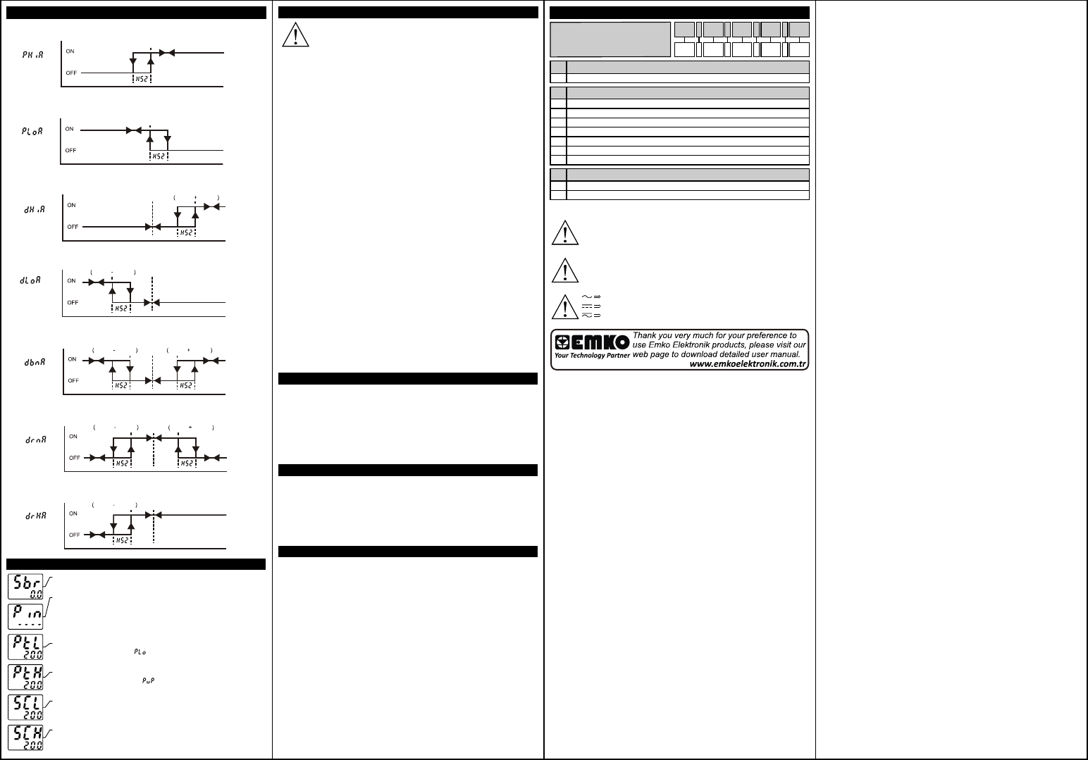
Alarm Types
Set 2
Alarm
Output
Process Value
Process H�gh
Alarm
Process Low
Alarm
Set 2
Alarm
Output
Process Value
Dev�at�on Low
Alarm
Alarm
Output
Process Value
Set 1Set 1 Set 2
Dev�at�on H�gh
Alarm
Set 1 Set 1 Set 2
Alarm
Output
Process Value
Dev�at�on Band
Alarm
Set 1 Set 2 Set 1 Set 1 Set 2
Alarm
Output
Process Value
Dev�at�on Range
Alarm
Set 1 Set 2 Set 1 Set 1 Set 2
Alarm
Output
Process Value
Set 1 Set 2 Set 1
Dev�at�on Range
H�gh Alarm
Alarm
Output
Process Value
1-Sensor fa�lure �n analog �nputs. Sensor connect�on �s wrong or there
�s no sensor connect�on.
a
2-If programm�ng sect�on enter�ng password �s d�fferent from “0” and
user accesses to the parameter by enter button w�thout enter�ng the
password and wants to change a parameter, the warn�ng message �s
shown on the bottom d�splay as shown on the left. Dev�ce does not
allow to do any changes w�thout enter�ng the password correctly.
a
3-If value that �s read from the analog �nput �s lower than process set
low l�m�t parameter value ( ), value on the top d�splay starts to bl�nk
as shown on the p�cture.
a
4-If value that �s read from the analog �nput �s h�gher than process set
h�gh l�m�t parameter value ( ), value on the top d�splay starts to
bl�nk as shown on the p�cture.
a
5-If value that �s read from the analog �nput �s lower than sensor scale
low l�m�t, value on the top d�splay starts to bl�nk as shown on the
p�cture.
a
6-If value that �s read from the analog �nput �s h�gher than sensor scale
h�gh l�m�t, value on the top d�splay starts to bl�nk as shown on the
p�cture.
PO2
PO1
AL1
AL2
°C
°F
/
Error Messages
PO2
PO1
AL1
AL2
°C
°F
/
PO2
PO1
AL1
AL2
°C
°F
/
PO2
PO1
AL1
AL2
°C
°F
/
PO2
PO1
AL1
AL2
°C
°F
/
PO2
PO1
AL1
AL2
°C
°F
/
Before comm�ss�on�ng the dev�ce, parameters must be set �n
accordance w�th des�red use. Incomplete or �ncorrect conf�gurat�on
can cause dangerous st�uat�ons.
Because of l�m�ted mechan�cal l�fe of relay output contact, SSR
output �s recommended wh�ch the dev�ce use PID control algor�tm.
The dev�ce w�th ON/OFF control algor�tm, hysteres�s parameter must
be set a su�table value for your system, to avo�d too much relay
sw�tch�ng.
Vac,
Vdc,
Vdc or Vac can be appl�ed
Order�ng Informat�on
Eco LITE ( 48x48 DIN 1/16 )
D�mens�on
48x48 DIN 1/16
A
4
A
4 .
B
.
C
.
D
0 .
E
0
Outputs-1
1R
1 x Relay Output (5A@250VV at Res�st�ve Load) (NO,C)
C
2R
2 x Relay Output (5A@250VV at Res�st�ve Load) (NO,NO,C)
Supply VoltageB
10...30VZ
115VV (±%15) 50/60Hz
230VV (±%15) 50/60Hz
3
5
6
100-240VV 50/60Hz1
24VV (±%15) 50/60Hz
Customer
7
9
24VW (±%15) 50/60Hz2