
User Guide
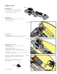


The diagrams shown here all use the B162 (T3) switch that is
designed for Fender Telecaster*. When the switch is mounted to the
Tele control plate the Bridge and Neck Pickup input legend will be as it
says on the PC Board. If you use the B162 for another type of guitar,
you might have the PC Board facing the other direction. If this is so,
simply reverse the inputs. Use the BRG input for the Neck Pickup, and
use the NEK input for the Bridge Pickup.
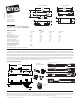
Diagram #10
This diagram shows the wiring for the standard installation included
in these instructions.
Diagram #11
This diagram shows discrete controls with a volume control and
passive tone control. It is shown mounted to the Tele control plate,
but the wiring would be the same for any two pickup guitar using the
T3 switch. But as stated above, dpending on which direction you install
the selection switch the pickup inputs might need to be reversed.
Diagram #12
This diagram shows an active tone control added to the guitar. The
control could be any EMG Active control, like the SPC, RPC, EXG, VLPF
or a BT Control. This installation would be similar to an EMG-X
installation using the VLPF Active tone control.
* Tele and Telecaster are registered Trademarks of FMIC
T / TC SET Page 4
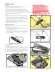
Diagram #13
If the instrument has a Battery Holder:
If your instrument has a 9 or 18-Volt battery holder you can still
use the EMG Connectors to supply power to the pickups.
Simply cut and strip the wires from the battery clip provided.
Twist the wires together (Red to Red and Black to Black) and
use the shrink tubing included to cover the connections.
Soldering the wires is recommended.
9/18 VOLT
BATTERY
HOLDER
Cover these connections with the
shrink tubing provided.
BLACK to RING terminal
of the Output Jack
RED to BATTERY OR PICKUP BUSS
BRIDGE PICKUP
NECK PICKUP
BRIDGE PICKUP
NECK PICKUP
BRIDGE PICKUP
NECK PICKUP
Installation Instructions:
EMG Models: T & TC SET
Alternate diagrams:
TIP
RING
SLEEVE
Diagram #14
FROM TONE
OR VOLUME
BATTERY
NEG (-)
RED to BATTERY BUSS
Soldering to the 152B Panel Jack:
If your instrument has a long Panel Jack like the one below
you will have to solder the output cable as shown.
Ground (Black) to the Sleeve
Signal (White) to the Tip
Battery Negative (Black) to the Ring
- 9V +
- 9V +
- 9V +
- 9V +
Diagram #10
Diagram #11
Diagram #12