
Instruction Manual


5. Unscrew the retaining nut (key 15M) from the bonnet.
Pushing on the stub shaft (key 15J) will expose the bonnet
parts including the packing.
6. Besides the packing, the liner bushings (keys 15B and 15K)
should be replaced. Lubricate the packings with Multi-
purpose PTFE lubricant.
7. Reassemble in reverse order. Replace cap screw (key 15R)
using 30 to 35 inch-pounds / 3.4 to 4.0 N•m torque.
8. Before replacing the gland assembly, replace the
O-ring (key 16) with the proper material matching
the main seals. The standard Types C471 and C477
material is Nitrile (NBR).
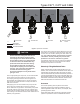
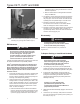
9. Orient Cam and stub shaft (See Figure 4)
Before reassembling the gland assembly into the body,
make sure the operating lever can move freely with the new
parts installed. Then, correctly orient the cam to the stub
shaft. Incorrect orientation will result in either:
a. Not being able to open the internal valve or
b. Only being able to partially open the internal valve
which will cause the valve’s excess ow feature to
close prematurely
Refer to Figure 4. Looking at the end of the stub shaft (C)
that the lever or actuator attaches to:
1. The cam prole on the opposite end of the shaft should
be up and the cam pointing to the left.
2. The hole (B) through the stub shaft that the lever/
actuator attaches to should be oriented in a NE to SW
position with N being at the top.
3. The 2 gland wings should be at the top as shown
in Figure 4.
4. The lever should be oriented as shown and the cotter pin
run through hole (B).
10. Once proper orientation of the cam is conrmed:
a. Reinstall the washers (key 55) and nuts (key 59) and
torque to 90 to 100 inch-lbs / 10 to 11 N•m. Reinstall
actuator or latch if applicable.
b. If reusing the cap screws, reinstall the actuator or latch if
applicable before installing the cap screws and washers.
Torque to 90 to 100 inch-lbs / 10 to 11 N•m.
c. If installing new studs, install the long studs (key 57) in
the top-most hole locations and the short stud (key 58) in
the bottom-most location. Secure the gland to the body
with the rst set of washers (key 12) and nuts. Reinstall
actuator or latch if applicable or cover two long studs with
protective cap (key 60) if available.
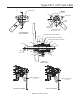
To Replace Seat Discs
1. Remove the valve from the tank.
2. Remove the cotter pin (key 14, Figure 5) and unscrew
the hex nut (key 13).
3. Remove both disc holders (keys 6 and 12) from the
stem (key 2).
4. Unscrew the screws (keys 9 and 4 for 2-inch / DN 50,
6 for 3-inch / DN 80) holding the disc retainer (key 8) to
replace the main seat disc.
5. Examine both seat discs (keys 7 and 11) and replace
if necessary.
6. If the excess ow spring (key 3) is changed, replace the
nameplate or stamp the body with the new type number.
7. Always replace the sealing washer (key 23).
8. a. Reassemble in reverse order. Tighten the screws
(key 9) using 20 inch-pounds / 2.2 N•m torque to
install the disc retainer (key 8) properly.
CAUTION
Failure to properly center the disc retainer
to the disc holder may result in improper
function of the valve.
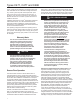
Important
During replacement of the seat disc, use P/N
GE45079X012 provided to center the disc
retainer to the disc holder (See Figure 3).
Line up holes and insert screws. Keep the
alignment tool inserted until all of the screws
are tightened to specication.
Alternately, the stem assembly (key 2) and
spring seat (key 4) may be used as shown
in Figure 3 to perform this alignment. After
assembly, check to make sure there is no
interference of the spring seat and disc retainer
when the valve is in the excess ow position.
b. Apply Medium-Strength Threadlocker on the stem
threads before installing the hex nut (key 13).
Parts Ordering
Important
Use only genuine Fisher
®
replacement
parts. Components that are not supplied
by Emerson™ should not, under any
circumstances, be used in any Fisher valve,
because they will void your warranty, might
adversely affect the performance of the valve
and could give rise to personal injury and
property damage.
When corresponding about this equipment, always reference
the equipment type number found on the nameplate.
When ordering replacement parts, reference the complete
11-character part number for each needed part.
Types C471, C477 and C486
8