
Instruction Manual


the internal valve. If piping is cold allow it to warm to
ambient temperature.
b. Refer to CFR 49 Section 180 Appendix B for Meter
Creep Test Methods.
3. All operating controls should be inspected and cleaned
and oiled. The controls should be checked to see that
they fully open—but not over-travel—the internal valve
operating lever and operate freely to close the valve.
4. Standard construction internal valves must
be removed if the container is to be steam cleaned.
Heat can damage the valve’s seats and seals.
5. Standard construction internal valves are not designed
for water service. Immediately after a container is
hydrostatically tested, remove all water and allow the
container to thoroughly dry out.
Disassembly
!
WARNING
Tank pressure must be released before
removing the valve from the container. Failure
to do so could result in personal injury.
Numbers in parenthesis refer to key numbers in
Figures 3 to 7.
To Replace Packing or Install Gland Hardware
!
WARNING
Downstream pressure must be released
before removing the screws holding the gland
assembly to the internal valve body. Failure to
do so could result in personal injury.
1. The packing (keys 15F, G and H) can be replaced with
product in the tank by closing the operating lever (key 18)
and blowing down the downstream pressure in the system.
2. If using Screw-Type hardware, remove the three cap
screws (key 17) holding the bonnet assembly to the body.
If using the current Stud-Type hardware, remove the
nuts (key 59) and washers (key 55) holding the bonnet
assembly to the body.
Note
If working on a valve equipped with a
pneumatic actuator, please refer to the
corresponding actuator Instruction Manual for
proper removal procedures.
3. Rotate the entire bonnet assembly slightly to remove it from
the body.
4. Unscrew the cap screw (key 15R) from the stub shaft
(key 15J) and remove the operating lever by taking out
the cotter pin (key 19).
Maintenance
CAUTION
Do not use these internal valves if they leak,
fail to work properly or have been damaged
or have missing parts. Prompt repairs
should be made by a properly trained service
person. Continued use without repair can
create a hazardous or injurious situation.
A simple preventative maintenance program for the valve and
its controls will eliminate a lot of potential problems.
Fisher
®
recommends these steps be conducted once a
month. Also refer to the Department of Transportation
(DOT) CFR 49 Sections 180.416 and 180 Appendix A and
B which specify monthly maintenance and inspections
tests for cargo tank service internal valves and their
actuation controls.
1. Inspect the operating lever to see that it operates freely
and that there is no leakage around the retainer nut.
If there is sticking or leakage, replace the packing and
bushings. Refer to Replacing Packing.
2. Check for tight closure of the seat discs. Any detected
leakage, which is normally caused by disc wear or dirt,
scale or debris embedded in the disc, requires that the
internal valve be removed from service and repaired.
Repair most often requires the replacement of valve
discs. To check for leakage:
a. Close the internal valve and exhaust downstream
pressure. Close the rst valve downstream from the
internal valve and note any pressure buildup, using
a pressure gauge, between the closed valve and
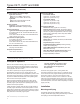
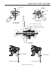
Figure 3. Use Tool Provided or Spring Seat (key 4) and Stem
Assembly (key 2) to Align Disc Retainer (key 8)
Types C471, C477 and C486
6