
Instruction Manual


CAUTION
Excess ow valve closing ow rates are not
the same for half and full couplings. Verify
the coupling for the desired excess ow rate.
Do not install the valve in any piping tending
to restrict the valve inlet because this may
prevent the excess ow valve from closing.
Do not install the valve with such extreme
torque that the coupling can cut threads into
the valve. This could cause valve distortion
and affect the internal working parts.
Do not use PTFE tape as it may cause thread
galling to occur.
Use an appropriate pipe compound, on the male threads
of the internal valve and pipeline. Pull the valve into
the coupling hand tight and then wrench tighten it for
approximately two additional turns. Larger size valves
may require an additional amount of torque to obtain a
leak-free connection.
Keep piping from the valve outlet to the pump full size
and as short as possible with a minimum number of
bends. Reduction in pipe size to suit smaller pump inlets
should be made as close to the pump as possible using
forged reducers (swage nipples) or venturi tapers rather
than bushings. This assures minimum flow resistance and
efficient pump operation.
The valves have a break off section below the inlet pipe
thread which is intended to permit the lower valve body
to shear off in an accident, leaving the valve seat in the
tank. The break off section is designed for container
installations and will probably not provide shear
protection if the valve is installed in a pipeline.
A hydrostatic relief valve does not need to be installed
adjacent to the valve since the internal valve relieves
excessive line pressure into the tank.
Selectively Filling Manifolded Tanks
Fisher
®
internal valves provide positive shutoff only in one
direction, from out of the tank to downstream of the valve. The
internal valves are designed to allow gas to ow into a tank
when the downstream line pressure exceeds tank pressure. If
you want to selectively ll one or more of the other tanks in a
tank manifold system, you must place a positive shutoff valve
downstream of the internal valve, otherwise, all tanks will be
lled at the same time and at about the same rate.
Actuators
The remote operating control system for the valve is
extremely important and it must be installed to conform
with the applicable codes. DOT MC331, for example, most
generally applies for trucks.
Fisher offers both cable controls and pneumatic actuator
systems to operate the C470 and C486 Series internal
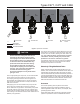
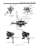
Figure 2. Operational Schematic
M1170
VALVE CLOSED
1 2 3 4
JET BLEED OPEN VALVE OPEN EXCESS FLOW VALVE
CLOSED
LIMITED BLEED
VALVE OPEN FLOW
JET BLEED EQUALIZATION
JET
BLEED
JET
BLEED
FLOW
LIMITED
BLEED
LIMITED
BLEED
FLOW
3
Types C471, C477 and C486