
Data Sheet


Bulletin LP-7:C471/C477
3
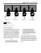
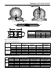
Figure 2. Typical Operational Schematic
Principle of Operation
Refer to the operational schematic, Figure 2. In view #1, the
valve is held closed by both tank pressure and the valve’s
closing spring. There is no leakage past the resilient seats
in the poppet to the valve outlet. The valve is opened by
moving the operating lever to approximately midpoint in its
70° travel (view #2). This allows the cam to place the rapid
equalization portion of the valve stem in the pilot opening,
permitting a larger amount of product to bleed downstream
than if the operating lever were moved to the full open
position. When tank and downstream pressure are nearly
equal after a few seconds, the excess ow spring pushes
open the main poppet (view #3) and the operating lever can
be moved to the full open position.
Note
If tank pressure is greater than the valve’s
outlet pressure, the main poppet will remain
in the closed position. If valve outlet piping
is closed off by other valves, however,
product bleeding through the pilot will
increase until it nearly equals tank pressure
and the main poppet opens. The main
poppet will not open if valve outlet piping is
not closed off so that the outlet pressure can
approach tank pressure.
Once the main poppet opens, a ow greater than the
valve’s excess ow spring rating or a sufcient surge in
ow forces the main poppet closed against the excess ow
spring (view #4). The pilot valve allows a small amount of
product to bleed, but much less than view #2 where the
rapid equalization portion of the stem is placed in the pilot
opening. When the operating lever is moved to the closed
position, the valve closes completely and seals tightly
(view #1).
LIMITED BLEED
VALVE OPEN FLOW
JET BLEED EQUALIZATION
VALVE CLOSED
1 3 4
JET BLEED OPEN VALVE OPEN EXCESS FLOW VALVE
CLOSED
JET
BLEED
JET
BLEED
FLOW
LIMITED
BLEED
LIMITED
BLEED
FLOW
M1170