
Satellite Radio User Manual


18
1. Refer to Micro Motion’s 9-Wire Flowmeter Cable Preparation and
Installation Guide for instructions on cable shielding and
preparation:
• At the sensor end, follow the instructions for your cable type.
• At the core processor end, follow the instructions for your cable
type with an MVD transmitter.
2. To connect the wires, refer to Micro Motion’s 9-Wire Flowmeter
Cable Preparation and Installation Guide and follow the instructions
for your sensor with an MVD transmitter. Additional information for
connecting the wires at the core processor is provided below:
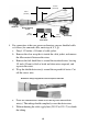
a. Identify the components shown in Figure 10.
a. Remove the core processor’s end-cap.
b. Insert the 9-wire cable through the conduit opening.
c. Connect the wires to the plugs supplied with the core processor.
d. Insert the plugs into the sockets inside the lower conduit ring. See
Figure 15.
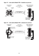
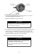
Figure 15. 9-wire cable to core processor
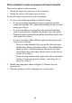
3. Ground the cable. If using jacketed cable:
a. Ground the shield drain wires (the black wire) only on the core
processor end, by connecting it to the ground screw inside the
lower conduit ring. Do not ground to the core processor’s
mounting screw. Do not ground the cable at the sensor junction
box.
Brown
Red
Green
White
Blue
Gray
Orange
Violet
Yellow
Black
(Drains from
all wire sets)
Plug and
socket
Mounting screw
Blue
Gray
Orange
Red
Green
White
Brown
Violet
Yellow
Ground screw
Black
9-wire cable from
sensor
Core processor