Quick Reference Guide P/N 20001008, Rev. B August 2005 Model 3700 Transmitter (MVD) or Model 3350 Peripheral Installation Instructions for Field-Mount For technical support, phone the support center nearest you: • In the U.S.A., phone 1-800-522-MASS (1-800-522-6277) • In Canada and Latin America, phone (303) 527-5200 • In Asia, phone (65) 6770-8155 • In the U.K., phone 0800 - 966 180 (toll-free) • Outside the U.K.
BEFORE YOU BEGIN This quick reference guide explains basic installation guidelines for installing the Micro Motion® Model 3350/3700 MVD applications platform. For information on I.S. applications, refer to Micro Motion approval documentation. For complete instructions about configuration, maintenance, and service, refer to the instruction manual shipped with the transmitter. WARNING Improper installation in a hazardous area can cause an explosion.
European installations This Micro Motion product complies with all applicable European directives when properly installed in accordance with the instructions in this quick reference guide. Refer to the EC declaration of conformity for directives that apply to this product. The EC declaration of conformity, with all applicable European directives, and the complete ATEX Installation Drawings and Instructions are available on the web at www.micromotion.
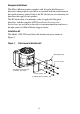
STEP 1. Choosing a location Choose a location for the transmitter based on the requirements described below. WARNING Improper installation in a hazardous area could cause an explosion. Install the transmitter in an area that is compatible with the rating on the approvals tag. See Figure 3. Environmental requirements Install the Model 3350/3700 according to specified limits: • Ambient temperature: –4 to +140 °F (–20 to +60 °C) Dimensions See Figures 2, 3, and 4 for Model 3350/3700 dimensions.
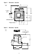
Figure 2. Dimensions – face view 12 (305) inches (mm) 11 (279) 4 x 5/16-inch (9 mm) diameter 9 3/16 (234) 2 13/16 (71) 4 (102) Mounting bracket can be rotated as needed 3 5/8 (92) Display cover can be rotated as needed 6 (152) Figure 3.
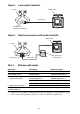
Figure 4. Dimensions – conduit openings view inches (mm) 2 x 15/16 (24) 1 7/8 (48) 2 x 2 13/17 (71) Case ground 5 x 3/4–14 NPT or 5 x M20 x 1.5 – 6H 10 3/8 (265) 7 1/2 (191) 5 3/4 (147) Mounting surface Cable lengths Maximum cable length from the sensor to the Model 3700 transmitter depends on the installation type and cable type: • 4-wire remote transmitter: see Figure 5, then refer to Table 1 for maximum length of the 4-wire cable.
Figure 5. 4-wire remote transmitter Sensor Model 3700 4-wire cable Core processor (standard or enhanced) Figure 6. Remote core processor with remote transmitter Model 3700 Sensor 4-wire cable Table 1.
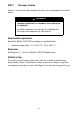
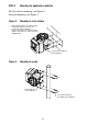
STEP 2. Preparing conduit openings for ATEX Zone 1 If the Model 3350/3700 carries an ATEX Zone 1 approval: 1. Remove thread protectors from conduit openings (see Figure 7). 2. Install factory-supplied cable glands or user-supplied EExe cable entry devices in conduit openings that are in use. 3. Install EExe plugs in conduit openings that are not in use. STEP 3.
STEP 4. Mounting the applications platform For flat-surface mounting, see Figure 8. For pole mounting, see Figure 9. Figure 8. • • • Mounting to a flat surface Mount all four bolts to the same surface. If mounting surface is not flat, use washers to shim the bracket. Do not secure bolts to separate beams, girders, wall studs, etc., which can move independently. 4 x 5/16-inch or M8 bolt (user-supplied) Figure 9.
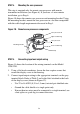
STEP 5. Mounting the core processor This step is required only for remote core processor with remote transmitter installations (see Figure 6). If you have a 4-wire remote installation, go to Step 6. Figure 10 shows the remote core processor and mounting bracket. Using the mounting bracket, mount the core processor in a location compatible with the cable length requirements discussed in Step 1. Figure 10.
Figure 11. Wiring terminals Circuit board compartment Lockout device (not supplied with all units) Non-intrinsically safe input/output wiring terminals (gray terminal block) Intrinsically safe sensor wiring terminals (blue terminal block) Wiring compartment Should remain closed while power is on Power supply ground Label for sensor wiring terminals (see Figure 12) Label for input/output wiring terminals Display cover Table 2.
Figure 12. Wiring terminal labels Model 3350/3700 with AC power supply Model 3350/3700 with DC power supply Terminal 9: line (L or L2) Terminal 9: positive Terminal 10: neutral (N or L1) Terminal 10: negative STEP 7. Connecting the Model 3700 to the sensor If you are installing the Model 3350 applications peripheral, this step is not required. Go to Step 8. To connect the Model 3700 transmitter to a Micro Motion sensor, follow the instructions in this section.
Installation options The Model 3700 can be wired to the sensor in either of the following configurations: • 4-wire remote transmitter (requires a 4-wire cable; see Figure 5 and Wiring instructions for 4-wire remote installations) • Remote core processor with remote transmitter (requires both a 4-wire and a 9-wire cable; see Figure 6 and Wiring instructions for remote core processor with remote transmitter) Wiring instructions for 4-wire remote installations 1.
Figure 13. 4-wire cable to Model 3700 – standard core processor Core processor terminals VDC+ (Red) RS-485B (Green) 4-wire cable Maximum cable length: see Table 1 Model 3700 terminals blue terminal block (see Figure 11) User-supplied or factory-supplied cable VDC– (Black) RS-485A (White) 16 RS-485B (Green) 15 RS-485A (White) 14 VDC– (Black) 13 VDC+ (Red) Figure 14.
Wiring instructions for remote core processor with remote transmitter There are two phases to this procedure: • Wiring the remote core processor to the transmitter • Wiring the sensor to the remote core processor To wire the remote core processor to the transmitter: 1. Use one of the following methods to shield the wiring: • If you are installing unshielded wiring in continuous metallic conduit that provides 360° termination shielding for the enclosed wiring, go to Step 6.
4 1/2 in (114 mm) 3/4 in (19 mm) Gland nut Gland clamping insert 7/8 in (22 mm) 7/8 in (22 mm) Gland body Shielded heat shrink 4. For connection at the core processor housing, prepare shielded cable as follows (for armored cable, omit steps d, e, f, g): a. Strip 4 1/2 inches (114 mm) of cable jacket. b. Remove the clear wrap that is inside the cable jacket, and remove the filler material between the wires. c.
Shielded heat shrink completely covers exposed drain wires g. Position gland clamping insert so the interior end is flush with the heat shrink. h. Fold the cloth shield or braid and drain wires over the clamping insert and approximately 1/8 inch (3 mm) past the O-ring. i. Install the gland body into the core processor housing conduit opening. 5. Insert the wires through the gland body and assemble the gland by tightening the gland nut. 6. Identify the wires in the 4-wire cable.
Power supply + (Red wire) RS-485B (Green wire) RS-485A (White wire) Power supply – (Black wire) Core processor housing internal ground screw • For connections to earth ground (if core processor cannot be grounded via sensor piping and local codes require ground connections to be made internally) • Do not connect shield drain wires to this terminal 7. Reinstall and tighten the core processor lid. WARNING Twisting the core processor will damage the sensor. Do not twist the core processor. 8.
1. Refer to Micro Motion’s 9-Wire Flowmeter Cable Preparation and Installation Guide for instructions on cable shielding and preparation: • At the sensor end, follow the instructions for your cable type. • At the core processor end, follow the instructions for your cable type with an MVD transmitter. 2. To connect the wires, refer to Micro Motion’s 9-Wire Flowmeter Cable Preparation and Installation Guide and follow the instructions for your sensor with an MVD transmitter.
If using shielded or armored cable: a. Ground the shield drain wires (the black wire) only on the core processor end, by connecting it to the ground screw inside the lower conduit ring. Do not ground to the core processor’s mounting screw. Do not ground the cable at the sensor junction box. b. Ground the cable braid on both ends, by terminating it inside the cable glands. 4.
Connect the Model 3350/3700 to a power supply as follows: 1. Use 18 to 12 AWG (0,75 to 4,0 mm2) wire. 2. Using a flat-head screwdriver, loosen the captive screws that secure the display cover to the housing. 3. Ground the transmitter as follows: • Connect the ground wire to the green screw (power supply ground; see Figure 11). • Connect the power supply ground wire directly to earth ground. • Keep all ground leads as short as possible. • Ground wiring must have less than 1 ohm impedance. 4.
21
22
©2005, Micro Motion, Inc. All rights reserved. P/N 20001008, Rev. B *20001008* Visit us on the Internet at www.micromotion.com Micro Motion Inc.