
Instruction Manual


Table Of Contents
Solatron™ Plus Series Instruction Manual • 7
4.4ElectricalConnections
The unit is designed to operate from a voltage source as indicated on the name-
plate and to power loads where maximum continuous kVA does not exceed the
nameplate indication. EnsurethatthesourcevoltageandmaximumloadkVA
conform to the nameplate rating on the front of the unit.
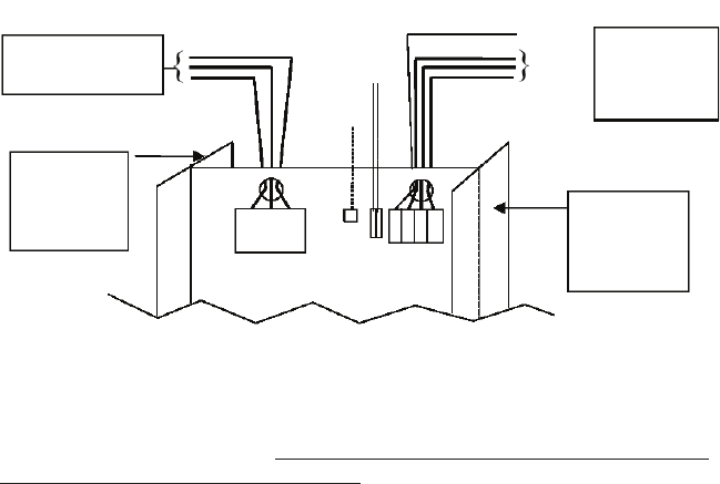
The unit is installed much like a transformer, between the supply lines and the
load(s) being protected as shown in Figure 2.
4.4.1ConduitEntry/ExitLocations
The conduit entry/exit holes must be punched in the sides or back of the rear
portion of the enclosure (the side with the transformers), so that the power
conductors run to the circuit breaker and output lugs through the hole(s) provided
in the barrier panel. See Figure 2.
3-phase source conductors
Must conform to nameplate voltage
No phase order is necessary
ATTENTION!
Conduit entry through
the rear portion of the
enclosure only!
ATTENTION!
Conduit entry through
the rear portion of the
enclosure only!
Output connections for
units rated >500 A output
current are made directly
to labeled transformer bus
in the rear of the enclosure
TO LOAD
INPUT C/B
GROUND
REMOTE ALARM
NEUTRAL CONNECTION
TO LOAD IF REQUIRED
Figure 2. Electrical Connections (3-phase unit shown)
NOTE: Each ac output power circuit shall be provided with overcurrent protection
for all ungrounded conductors. It is the responsibility of the purchaser to provide
provisions for this overcurrent protection. The overcurrent protection device shall
be a circuit breaker or fuse for use as a branch circuit protection. The voltage
rating of the protective device for a three-phase system shall be based on the
phase-to-phase voltage. The rating of the overcurrent protective device must
meet the requirements of the National Electrical Code Article 240. Failure to
accomplishthiswillvoidtheUL1012listing.