
Switch User Manual
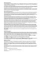
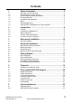
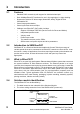
Table Of Contents
- Contents
- 1 Safety Information
- 2 Introduction
- 3 Mechanical Installation
- 4 Electrical Installation
- 5 Getting Started
- 6 Protocols
- 7 Drive profile (DSP-402) support
- 7.1 0x6040 Controlword
- 7.2 0x6041 Statusword
- 7.3 Common profile features
- 7.3.1 Sequencing control
- 7.3.2 0x605A Quick stop option code
- 7.3.3 0x605B Shutdown_option_code
- 7.3.4 0x605C Disable_operation_option_code
- 7.3.5 0x605E Fault_reaction_option_code
- 7.3.6 0x6060 Modes_of_operation
- 7.3.7 0x6061 Modes_of_operation_display
- 7.3.8 0x6085 Quick_stop_deceleration
- 7.3.9 Profile units
- 7.3.10 0x608F Position_encoder_resolution
- 7.3.11 0x6091 Gear_ratio
- 7.3.12 0x6092 Feed_constant
- 7.3.13 Basic position control
- 7.3.14 0x6062 Position_demand_value
- 7.3.15 0x6064 Position_actual_value
- 7.3.16 0x60F4 Following_error_actual_value
- 7.3.17 0x60FB Position_control_parameter_set object
- 7.4 Interpolated position mode
- 7.5 vl velocity mode
- 7.5.1 0x6042 vl_target_velocity
- 7.5.2 0x6043 vl_velocity_demand
- 7.5.3 0x6044 vl_velocity_actual_value
- 7.5.4 0x6046 vl_velocity_min_max_amount
- 7.5.5 0x6047 vl_velocity_min_max
- 7.5.6 0x6048 vl_velocity_acceleration
- 7.5.7 0x6049 vl_velocity_deceleration
- 7.5.8 0x604A vl_velocity_quick_stop
- 7.5.9 0x604B vl_setpoint_factor
- 7.5.10 0x604C vl_dimension_factor
- 7.6 Profile Torque mode
- 7.7 Homing Mode
- 8 Advanced features
- 9 Diagnostics
- 9.1 Module identification parameters
- 9.2 Network configuration objects
- 9.3 Diagnostic parameters
- 9.4 Drive trip display codes
- 9.5 SM-EtherCAT module temperature
- 9.6 SM-EtherCAT serial number
- 9.7 SM-EtherCAT error codes
- 9.8 Critical task % free
- 9.9 Worst case critical task % free
- 9.10 FLASH file system % free
- 9.11 Updating SM-EtherCAT firmware
- 10 Quick Reference
- 11 Glossary Of Terms
- Index
SM-EtherCAT User Guide 9
Issue Number: 2 www.controltechniques.com
Safety
Information
Introduction
Mechanical
Installation
Electrical
Installation
Getting Started Protocols
Drive profile (DSP-402)
support
Advanced
features
Diagnostics
Quick
Reference
Glossary Of
Terms
Index
2.4.1 Date code format
The date code is split into two sections: a letter followed by a number.
The letter indicates the year and the number indicates the week number (within the
year) in which the Solutions Module was built.
The letters are alphabetical in order, starting with A in 1991 (B in 1992, C in 1993 etc.).
Example:
A date code of Q46 would correspond to week 46 of year 2007.
2.5 Conventions used in this guide
The configuration of the host drive and Solutions Module is done using menus and
parameters. A menu is a logical collection of parameters that have similar functionality.
In the case of a Solutions Module, the parameters will appear in menu 15 for the
Commander SK, in menu 15 or 16 for Affinity and in menu 15, 16 or 17 for the Unidrive
SP, Digitax ST and Mentor MP depending on the slot the module is fitted into. The menu
is determined by the number before the decimal point. The method used to determine
the menu or parameter is as follows:
•Pr xx.00 - signifies any menu and parameter number 00.
•Pr MM.xx - where MM signifies the menu allocated to the Solution Module
(this could be 15, 16 or 17 on the Unidrive SP, Digitax ST or Mentor MP, 15 or
16 on the Affinity, but will always be 15 on the Commander SK) and xx
signifies the parameter number.
All references in this manual to SM-Applications/Plus should also extend to SM-Applica-
tions Lite/Lite V2. The exceptions to this are references to SM-Applications/Plus input/
output, CTSync or the RS485 port, as these are not supported on SM-Applications Lite/
Lite V2. For full details of the differences see the SM-Applications Modules and Motion
Processors User Guide.
It is strongly recommended that the latest firmware be used where possible to ensure
that all features are supported.
NOTE
NOTE