
Switch User Manual
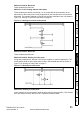
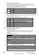
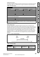
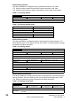
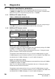
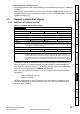
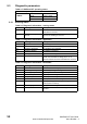
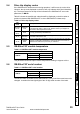
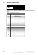
Table Of Contents
- Contents
- 1 Safety Information
- 2 Introduction
- 3 Mechanical Installation
- 4 Electrical Installation
- 5 Getting Started
- 6 Protocols
- 7 Drive profile (DSP-402) support
- 7.1 0x6040 Controlword
- 7.2 0x6041 Statusword
- 7.3 Common profile features
- 7.3.1 Sequencing control
- 7.3.2 0x605A Quick stop option code
- 7.3.3 0x605B Shutdown_option_code
- 7.3.4 0x605C Disable_operation_option_code
- 7.3.5 0x605E Fault_reaction_option_code
- 7.3.6 0x6060 Modes_of_operation
- 7.3.7 0x6061 Modes_of_operation_display
- 7.3.8 0x6085 Quick_stop_deceleration
- 7.3.9 Profile units
- 7.3.10 0x608F Position_encoder_resolution
- 7.3.11 0x6091 Gear_ratio
- 7.3.12 0x6092 Feed_constant
- 7.3.13 Basic position control
- 7.3.14 0x6062 Position_demand_value
- 7.3.15 0x6064 Position_actual_value
- 7.3.16 0x60F4 Following_error_actual_value
- 7.3.17 0x60FB Position_control_parameter_set object
- 7.4 Interpolated position mode
- 7.5 vl velocity mode
- 7.5.1 0x6042 vl_target_velocity
- 7.5.2 0x6043 vl_velocity_demand
- 7.5.3 0x6044 vl_velocity_actual_value
- 7.5.4 0x6046 vl_velocity_min_max_amount
- 7.5.5 0x6047 vl_velocity_min_max
- 7.5.6 0x6048 vl_velocity_acceleration
- 7.5.7 0x6049 vl_velocity_deceleration
- 7.5.8 0x604A vl_velocity_quick_stop
- 7.5.9 0x604B vl_setpoint_factor
- 7.5.10 0x604C vl_dimension_factor
- 7.6 Profile Torque mode
- 7.7 Homing Mode
- 8 Advanced features
- 9 Diagnostics
- 9.1 Module identification parameters
- 9.2 Network configuration objects
- 9.3 Diagnostic parameters
- 9.4 Drive trip display codes
- 9.5 SM-EtherCAT module temperature
- 9.6 SM-EtherCAT serial number
- 9.7 SM-EtherCAT error codes
- 9.8 Critical task % free
- 9.9 Worst case critical task % free
- 9.10 FLASH file system % free
- 9.11 Updating SM-EtherCAT firmware
- 10 Quick Reference
- 11 Glossary Of Terms
- Index
SM-EtherCAT User Guide 53
Issue Number: 2 www.controltechniques.com
Safety
Information
Introduction
Mechanical
Installation
Electrical
Installation
Getting Started Protocols
Drive profile (DSP-402)
support
Advanced
features
Diagnostics
Quick
Reference
Glossary Of
Terms
Index
0x2804 Freeze object
This object is used to configure the freeze function that can be used within the Homing
mode profile.
Table 7.55 Freeze object on page 53 specifies the object description.
Table 7.55 Freeze object
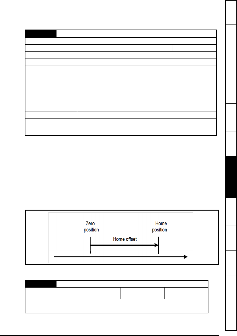
0x607C Home offset
This object indicates the configured difference between the zero position for the
application and the machine home position (found during homing). During homing the
machine home position is found and once the homing is completed the zero position is
offset from the home position by adding the home offset to the home position. All
subsequent absolute moves shall be taken relative to this new zero position. This is
illustrated in
Figure 7-11 Home offset definition on page 53. The value of this object
shall be given in user-defined position units. Negative values indicate the opposite
direction.
Figure 7-11 Home offset definition
Table 7.56 Home offset
0x2804
Freeze object
Sub-index 0
Access: RO Range: N/A Size: Unigned 8 Unit: N/A
Default: 2
Description: The number of the last sub-index in this object.
Sub-index 1
Access: RW Range: 0 to 1
Size: Unsigned 8 Unit: N/A
Default: 0
Description: Route the option freeze onto the drive. Setting a value of 1 here will route the option
digital input 0 onto the drive freeze line.
Sub-index 2
Access: RW
Range: 0 to 1 Size: Unsigned 8 Unit: N/A
Default: 0
Description: Option to drive freeze invert. Setting a value of 1 will invert the freeze signal routed onto
the drive from the option input 0 (if 0x2804, sub-index 1 is set to 1). This value will be read only on a
transition from 0 to 1 in sub-index 1.
0x607C Home offset
Access: RW
Range: -32768 to
+32767
Size: Signed 32
Unit: User-defined
position units
Default: 0
Description: Homing offset value.