
Switch User Manual
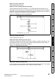
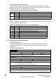
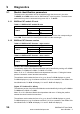
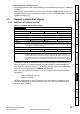
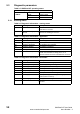
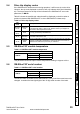
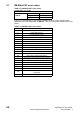
Table Of Contents
- Contents
- 1 Safety Information
- 2 Introduction
- 3 Mechanical Installation
- 4 Electrical Installation
- 5 Getting Started
- 6 Protocols
- 7 Drive profile (DSP-402) support
- 7.1 0x6040 Controlword
- 7.2 0x6041 Statusword
- 7.3 Common profile features
- 7.3.1 Sequencing control
- 7.3.2 0x605A Quick stop option code
- 7.3.3 0x605B Shutdown_option_code
- 7.3.4 0x605C Disable_operation_option_code
- 7.3.5 0x605E Fault_reaction_option_code
- 7.3.6 0x6060 Modes_of_operation
- 7.3.7 0x6061 Modes_of_operation_display
- 7.3.8 0x6085 Quick_stop_deceleration
- 7.3.9 Profile units
- 7.3.10 0x608F Position_encoder_resolution
- 7.3.11 0x6091 Gear_ratio
- 7.3.12 0x6092 Feed_constant
- 7.3.13 Basic position control
- 7.3.14 0x6062 Position_demand_value
- 7.3.15 0x6064 Position_actual_value
- 7.3.16 0x60F4 Following_error_actual_value
- 7.3.17 0x60FB Position_control_parameter_set object
- 7.4 Interpolated position mode
- 7.5 vl velocity mode
- 7.5.1 0x6042 vl_target_velocity
- 7.5.2 0x6043 vl_velocity_demand
- 7.5.3 0x6044 vl_velocity_actual_value
- 7.5.4 0x6046 vl_velocity_min_max_amount
- 7.5.5 0x6047 vl_velocity_min_max
- 7.5.6 0x6048 vl_velocity_acceleration
- 7.5.7 0x6049 vl_velocity_deceleration
- 7.5.8 0x604A vl_velocity_quick_stop
- 7.5.9 0x604B vl_setpoint_factor
- 7.5.10 0x604C vl_dimension_factor
- 7.6 Profile Torque mode
- 7.7 Homing Mode
- 8 Advanced features
- 9 Diagnostics
- 9.1 Module identification parameters
- 9.2 Network configuration objects
- 9.3 Diagnostic parameters
- 9.4 Drive trip display codes
- 9.5 SM-EtherCAT module temperature
- 9.6 SM-EtherCAT serial number
- 9.7 SM-EtherCAT error codes
- 9.8 Critical task % free
- 9.9 Worst case critical task % free
- 9.10 FLASH file system % free
- 9.11 Updating SM-EtherCAT firmware
- 10 Quick Reference
- 11 Glossary Of Terms
- Index
52 SM-EtherCAT User Guide
www.controltechniques.com Issue Number: 2
Use of controlword and statusword
The homing mode uses some bits of the controlword and the statusword for mode-
specific purposes.
Table 7.52 Definition of bits 4 and 8 of the controlword on page 52
defines the values for bits 4 and 8 of the controlword.
Table 7.52 Definition of bits 4 and 8 of the controlword
Table 7.53 Definition of bits 10 and 12 of the statusword on page 52 defines the values
for bits 10 and 12 of the statusword.
Table 7.53 Definition of bits 10 and 12 of the statusword
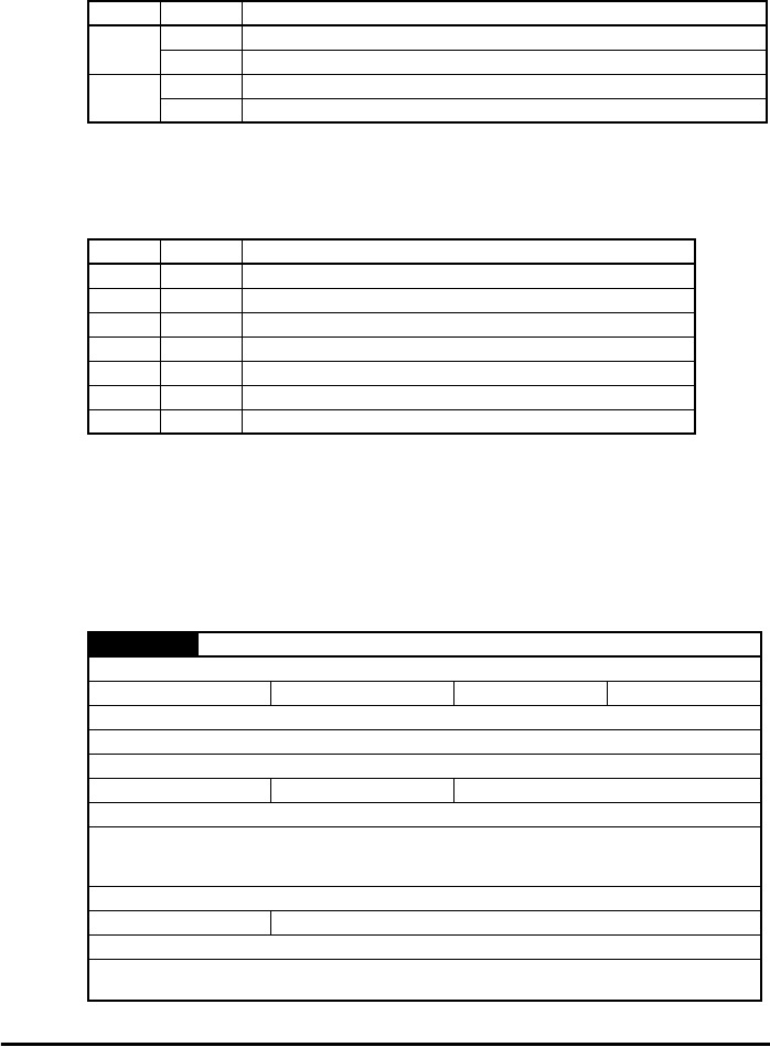
7.7.2 Homing mode object definitions
0x2803 Homing source
This object indicates the configured source of the homing switch used during the
homing procedure.
Table 7.54 Homing source on page 52 specifies the object
description.
Table 7.54 Homing source
Bit Value Definition
4
0 Do not start homing procedure.
1 Start or continue homing procedure.
8
0 Enable bit 4.
1 Stop axis according to halt option code (0x605D).
Bit 12 Bit 10 Definition
0 0 Homing procedure is in progress.
0 1 Homing procedure is interrupted or not started.
1 0 Homing is attained, but target is not reached.
1 1 Homing procedure was completed successfully.
0 0 Homing error occurred, velocity is not 0.
0 1 Homing error occurred, velocity is 0.
1 X Reserved.
0x2803 Homing source
Sub-index 0
Access: RO Range: N/A Size: Unigned 8 Unit: N/A
Default: 2
Description: The number of the last sub-index in this object.
Sub-index 1
Access: RW Range: 1 to 8
Size: Unsigned 8 Unit: N/A
Default: 5
Description: The source of the homing switch. This will specify a digital input as follows:
1 to 6 - The number of a Drive digital input
7 to 8 - SM-EtherCAT option module digital input 0 or 1
Sub-index 2
Access: RW
Range: 0 to 1 Size: Unsigned 8 Unit: N/A
Default: 0
Description: Use the feedback source freeze for homing. This will cause the freeze from the selected
feedback device to be used instead of the index (marker) pulse when it is required during homing.