
Switch User Manual
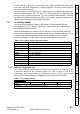
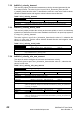
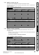
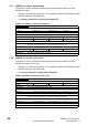
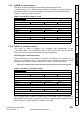
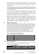
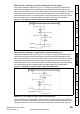
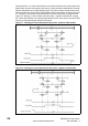
Table Of Contents
- Contents
- 1 Safety Information
- 2 Introduction
- 3 Mechanical Installation
- 4 Electrical Installation
- 5 Getting Started
- 6 Protocols
- 7 Drive profile (DSP-402) support
- 7.1 0x6040 Controlword
- 7.2 0x6041 Statusword
- 7.3 Common profile features
- 7.3.1 Sequencing control
- 7.3.2 0x605A Quick stop option code
- 7.3.3 0x605B Shutdown_option_code
- 7.3.4 0x605C Disable_operation_option_code
- 7.3.5 0x605E Fault_reaction_option_code
- 7.3.6 0x6060 Modes_of_operation
- 7.3.7 0x6061 Modes_of_operation_display
- 7.3.8 0x6085 Quick_stop_deceleration
- 7.3.9 Profile units
- 7.3.10 0x608F Position_encoder_resolution
- 7.3.11 0x6091 Gear_ratio
- 7.3.12 0x6092 Feed_constant
- 7.3.13 Basic position control
- 7.3.14 0x6062 Position_demand_value
- 7.3.15 0x6064 Position_actual_value
- 7.3.16 0x60F4 Following_error_actual_value
- 7.3.17 0x60FB Position_control_parameter_set object
- 7.4 Interpolated position mode
- 7.5 vl velocity mode
- 7.5.1 0x6042 vl_target_velocity
- 7.5.2 0x6043 vl_velocity_demand
- 7.5.3 0x6044 vl_velocity_actual_value
- 7.5.4 0x6046 vl_velocity_min_max_amount
- 7.5.5 0x6047 vl_velocity_min_max
- 7.5.6 0x6048 vl_velocity_acceleration
- 7.5.7 0x6049 vl_velocity_deceleration
- 7.5.8 0x604A vl_velocity_quick_stop
- 7.5.9 0x604B vl_setpoint_factor
- 7.5.10 0x604C vl_dimension_factor
- 7.6 Profile Torque mode
- 7.7 Homing Mode
- 8 Advanced features
- 9 Diagnostics
- 9.1 Module identification parameters
- 9.2 Network configuration objects
- 9.3 Diagnostic parameters
- 9.4 Drive trip display codes
- 9.5 SM-EtherCAT module temperature
- 9.6 SM-EtherCAT serial number
- 9.7 SM-EtherCAT error codes
- 9.8 Critical task % free
- 9.9 Worst case critical task % free
- 9.10 FLASH file system % free
- 9.11 Updating SM-EtherCAT firmware
- 10 Quick Reference
- 11 Glossary Of Terms
- Index
SM-EtherCAT User Guide 49
Issue Number: 2 www.controltechniques.com
Safety
Information
Introduction
Mechanical
Installation
Electrical
Installation
Getting Started Protocols
Drive profile (DSP-402)
support
Advanced
features
Diagnostics
Quick
Reference
Glossary Of
Terms
Index
Method 3 and 4: Homing on positive home switch and index pulse
Using these methods as shown in Figure 7-5 Homing on positive home switch and
index pulse on page 49, the initial direction of movement shall be dependent on the
state of the home switch. The home position shall be at the index pulse either to the left
or the right of the point where the home switch changes state. If the initial position is
sited so that the direction of movement shall reverse during homing, the point at which
the reversal takes place is anywhere after a change of state of the home switch.
Figure 7-5 Homing on positive home switch and index pulse
Method 5 and 6: Homing on negative home switch and index pulse
Using these methods as shown in Figure 7-6 Homing on negative home switch and
index pulse on page 49, the initial direction of movement shall be dependent on the
state of the home switch. The home position shall be at the index pulse either to the left
or the right of the point where the home switch changes state. If the initial position is
sited so that the direction of movement shall reverse during homing, the point at which
the reversal takes place is anywhere after a change of state of the home switch.
Figure 7-6 Homing on negative home switch and index pulse
Method 7 to 14: Homing on home switch and index pulse
These methods use a home switch, which is active over only a portion of the travel; in
effect the switch has a 'momentary' action as the axis's position sweeps past the switch.
Using the methods 7 to 10, the initial direction of movement shall be to the right, and