
Switch User Manual
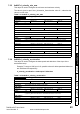
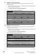
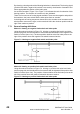
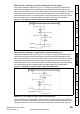
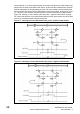
Table Of Contents
- Contents
- 1 Safety Information
- 2 Introduction
- 3 Mechanical Installation
- 4 Electrical Installation
- 5 Getting Started
- 6 Protocols
- 7 Drive profile (DSP-402) support
- 7.1 0x6040 Controlword
- 7.2 0x6041 Statusword
- 7.3 Common profile features
- 7.3.1 Sequencing control
- 7.3.2 0x605A Quick stop option code
- 7.3.3 0x605B Shutdown_option_code
- 7.3.4 0x605C Disable_operation_option_code
- 7.3.5 0x605E Fault_reaction_option_code
- 7.3.6 0x6060 Modes_of_operation
- 7.3.7 0x6061 Modes_of_operation_display
- 7.3.8 0x6085 Quick_stop_deceleration
- 7.3.9 Profile units
- 7.3.10 0x608F Position_encoder_resolution
- 7.3.11 0x6091 Gear_ratio
- 7.3.12 0x6092 Feed_constant
- 7.3.13 Basic position control
- 7.3.14 0x6062 Position_demand_value
- 7.3.15 0x6064 Position_actual_value
- 7.3.16 0x60F4 Following_error_actual_value
- 7.3.17 0x60FB Position_control_parameter_set object
- 7.4 Interpolated position mode
- 7.5 vl velocity mode
- 7.5.1 0x6042 vl_target_velocity
- 7.5.2 0x6043 vl_velocity_demand
- 7.5.3 0x6044 vl_velocity_actual_value
- 7.5.4 0x6046 vl_velocity_min_max_amount
- 7.5.5 0x6047 vl_velocity_min_max
- 7.5.6 0x6048 vl_velocity_acceleration
- 7.5.7 0x6049 vl_velocity_deceleration
- 7.5.8 0x604A vl_velocity_quick_stop
- 7.5.9 0x604B vl_setpoint_factor
- 7.5.10 0x604C vl_dimension_factor
- 7.6 Profile Torque mode
- 7.7 Homing Mode
- 8 Advanced features
- 9 Diagnostics
- 9.1 Module identification parameters
- 9.2 Network configuration objects
- 9.3 Diagnostic parameters
- 9.4 Drive trip display codes
- 9.5 SM-EtherCAT module temperature
- 9.6 SM-EtherCAT serial number
- 9.7 SM-EtherCAT error codes
- 9.8 Critical task % free
- 9.9 Worst case critical task % free
- 9.10 FLASH file system % free
- 9.11 Updating SM-EtherCAT firmware
- 10 Quick Reference
- 11 Glossary Of Terms
- Index
48 SM-EtherCAT User Guide
www.controltechniques.com Issue Number: 2
By choosing a homing method the following behaviour is determined: The homing signal
(positive limit switch, negative limit switch, home switch), the direction of actuation and
where appropriate the position of the index pulse.
An encircled number in Figure 7-3 to Figure 7-10 indicates the code for selection of this
homing position. The direction of movement is also indicated.
There are four sources of homing signal available: These are the negative and positive
limit switches, the home switch and the index pulse from an encoder.
In the diagrams of homing sequences shown below, the encoder count increases as the
axis's position moves to the right, in other words the left is the minimum position and the
right is the maximum position.
7.7.1 General homing definitions
Method 1: Homing on negative limit switch and index pulse
Using this method as shown in Figure 7-3 Homing on negative limit switch and index
pulse on page 48, the initial direction of movement shall be leftward if the negative limit
switch is inactive (here: low). The home position shall be at the first index pulse to the
right of the position where the negative limit switch becomes inactive.
Figure 7-3 Homing on negative limit switch and index pulse
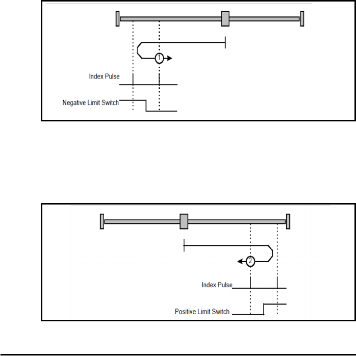
Method 2: Homing on positive limit switch and index pulse
Using this method as shown in Figure 7-4 Homing on positive limit switch and index
pulse on page 48, the initial direction of movement shall be rightward if the positive limit
switch is inactive (here: low). The position of home shall be at the first index pulse to the
left of the position where the positive limit switch becomes inactive.
Figure 7-4 Homing on positive limit switch and index pulse