
Switch User Manual

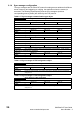
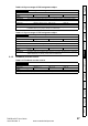
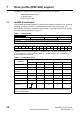
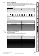
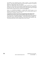
Table Of Contents
- Contents
- 1 Safety Information
- 2 Introduction
- 3 Mechanical Installation
- 4 Electrical Installation
- 5 Getting Started
- 6 Protocols
- 7 Drive profile (DSP-402) support
- 7.1 0x6040 Controlword
- 7.2 0x6041 Statusword
- 7.3 Common profile features
- 7.3.1 Sequencing control
- 7.3.2 0x605A Quick stop option code
- 7.3.3 0x605B Shutdown_option_code
- 7.3.4 0x605C Disable_operation_option_code
- 7.3.5 0x605E Fault_reaction_option_code
- 7.3.6 0x6060 Modes_of_operation
- 7.3.7 0x6061 Modes_of_operation_display
- 7.3.8 0x6085 Quick_stop_deceleration
- 7.3.9 Profile units
- 7.3.10 0x608F Position_encoder_resolution
- 7.3.11 0x6091 Gear_ratio
- 7.3.12 0x6092 Feed_constant
- 7.3.13 Basic position control
- 7.3.14 0x6062 Position_demand_value
- 7.3.15 0x6064 Position_actual_value
- 7.3.16 0x60F4 Following_error_actual_value
- 7.3.17 0x60FB Position_control_parameter_set object
- 7.4 Interpolated position mode
- 7.5 vl velocity mode
- 7.5.1 0x6042 vl_target_velocity
- 7.5.2 0x6043 vl_velocity_demand
- 7.5.3 0x6044 vl_velocity_actual_value
- 7.5.4 0x6046 vl_velocity_min_max_amount
- 7.5.5 0x6047 vl_velocity_min_max
- 7.5.6 0x6048 vl_velocity_acceleration
- 7.5.7 0x6049 vl_velocity_deceleration
- 7.5.8 0x604A vl_velocity_quick_stop
- 7.5.9 0x604B vl_setpoint_factor
- 7.5.10 0x604C vl_dimension_factor
- 7.6 Profile Torque mode
- 7.7 Homing Mode
- 8 Advanced features
- 9 Diagnostics
- 9.1 Module identification parameters
- 9.2 Network configuration objects
- 9.3 Diagnostic parameters
- 9.4 Drive trip display codes
- 9.5 SM-EtherCAT module temperature
- 9.6 SM-EtherCAT serial number
- 9.7 SM-EtherCAT error codes
- 9.8 Critical task % free
- 9.9 Worst case critical task % free
- 9.10 FLASH file system % free
- 9.11 Updating SM-EtherCAT firmware
- 10 Quick Reference
- 11 Glossary Of Terms
- Index
26 SM-EtherCAT User Guide
www.controltechniques.com Issue Number: 2
6.1.4 Sync manager configuration
The sync managers are the EtherCAT means for setting access attributes for different
areas of memory and triggering or notifying the application when the memory is
accessed. The following objects specify how the sync managers (and thus
corresponding memory areas) are utilised by the CoE protocol.
Table 6.17 Sync manager communication type object
0x1C00 Sync manager communication type
Sub-index 0 - number of sync manager channels used
Access: RO Range: N/A Size: 1 byte Unit: N/A
Default: 4
Description: The number of sync manager protocols used by the CoE protocol.
Sub-index 1 - Usage of sync manager 0
Access: RO Range: N/A Size: 1 byte Unit: N/A
Default: 1
Description: Sync manager 0 is used by CoE as the mailbox receive channel (master to slave).
Sub-index 2 - Usage of sync manager 1
Access: RO Range: N/A Size: 1 byte Unit: N/A
Default: 2
Description: Sync manager 1 is used by CoE as the mailbox send channel (slave to master).
Sub-index 3 - Usage of sync manager 2
Access: RO Range: N/A Size: 1 byte Unit: N/A
Default: 3
Description: Sync manager 2 is used by CoE as the process data output (RxPDOx - master to slave).
Sub-index 4 - Usage of sync manager 3
Access: RO Range: N/A Size: 1 byte Unit: N/A
Default: 4
Description: Sync manager 3 is used by CoE as the process data input (TxPDOs - slave to master).
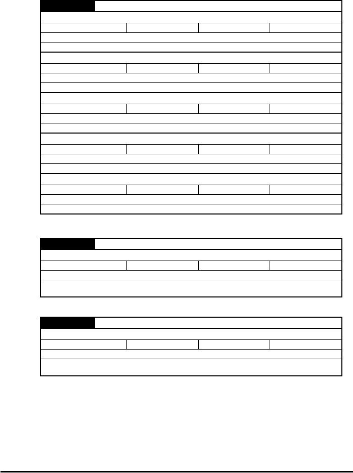
Table 6.18 Sync manager 0 PDO assignment object
0x1C10 Sync manager 0 PDO assignment
Sub-index 0
Access: RO Range: N/A Size: 1 byte Unit: N/A
Default: 0
Description: Number of assigned PDOs. The mailbox received sync manager can never have PDOs
assigned to it.
Table 6.19 Sync manager 1 PDO assignment object
0x1C11 Sync manager 1 PDO assignment
Sub-index 0
Access: RO Range: N/A Size: 1 byte Unit: N/A
Default: 0
Description: Number of assigned PDOs. The mailbox send sync manager can never have PDOs
assigned to it.