
Switch User Manual
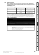

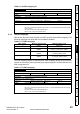
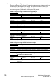
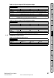
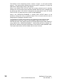
Table Of Contents
- Contents
- 1 Safety Information
- 2 Introduction
- 3 Mechanical Installation
- 4 Electrical Installation
- 5 Getting Started
- 6 Protocols
- 7 Drive profile (DSP-402) support
- 7.1 0x6040 Controlword
- 7.2 0x6041 Statusword
- 7.3 Common profile features
- 7.3.1 Sequencing control
- 7.3.2 0x605A Quick stop option code
- 7.3.3 0x605B Shutdown_option_code
- 7.3.4 0x605C Disable_operation_option_code
- 7.3.5 0x605E Fault_reaction_option_code
- 7.3.6 0x6060 Modes_of_operation
- 7.3.7 0x6061 Modes_of_operation_display
- 7.3.8 0x6085 Quick_stop_deceleration
- 7.3.9 Profile units
- 7.3.10 0x608F Position_encoder_resolution
- 7.3.11 0x6091 Gear_ratio
- 7.3.12 0x6092 Feed_constant
- 7.3.13 Basic position control
- 7.3.14 0x6062 Position_demand_value
- 7.3.15 0x6064 Position_actual_value
- 7.3.16 0x60F4 Following_error_actual_value
- 7.3.17 0x60FB Position_control_parameter_set object
- 7.4 Interpolated position mode
- 7.5 vl velocity mode
- 7.5.1 0x6042 vl_target_velocity
- 7.5.2 0x6043 vl_velocity_demand
- 7.5.3 0x6044 vl_velocity_actual_value
- 7.5.4 0x6046 vl_velocity_min_max_amount
- 7.5.5 0x6047 vl_velocity_min_max
- 7.5.6 0x6048 vl_velocity_acceleration
- 7.5.7 0x6049 vl_velocity_deceleration
- 7.5.8 0x604A vl_velocity_quick_stop
- 7.5.9 0x604B vl_setpoint_factor
- 7.5.10 0x604C vl_dimension_factor
- 7.6 Profile Torque mode
- 7.7 Homing Mode
- 8 Advanced features
- 9 Diagnostics
- 9.1 Module identification parameters
- 9.2 Network configuration objects
- 9.3 Diagnostic parameters
- 9.4 Drive trip display codes
- 9.5 SM-EtherCAT module temperature
- 9.6 SM-EtherCAT serial number
- 9.7 SM-EtherCAT error codes
- 9.8 Critical task % free
- 9.9 Worst case critical task % free
- 9.10 FLASH file system % free
- 9.11 Updating SM-EtherCAT firmware
- 10 Quick Reference
- 11 Glossary Of Terms
- Index
SM-EtherCAT User Guide 21
Issue Number: 2 www.controltechniques.com
Safety
Information
Introduction
Mechanical
Installation
Electrical
Installation
Getting Started
Protocols
Drive profile (DSP-402)
support
Advanced
features
Diagnostics
Quick
Reference
Glossary Of
Terms
Index
6.1.2 RxPDO mappings
Objects with indices from 0x1600 to 0x17FF specify receive PDO mappings. The
mappings from DSP-402 are included as standard (the PDO mappings will have the
following default values):
The RxPDO mappings objects are defined below. Each mapping object has the
maximum number of sub-indices (each representing an object mapped to a PDO)
defined in the XML configuration file (specified as “CF” in the descriptions below).
Table 6.6 RxPDO mappings
PDO number Mapping object index Mapping object name
1 0x6040 controlword
2 0x6040
0x6060
controlword
modes of operation
6 0x6040
0x6042
controlword
vl_target _velocity
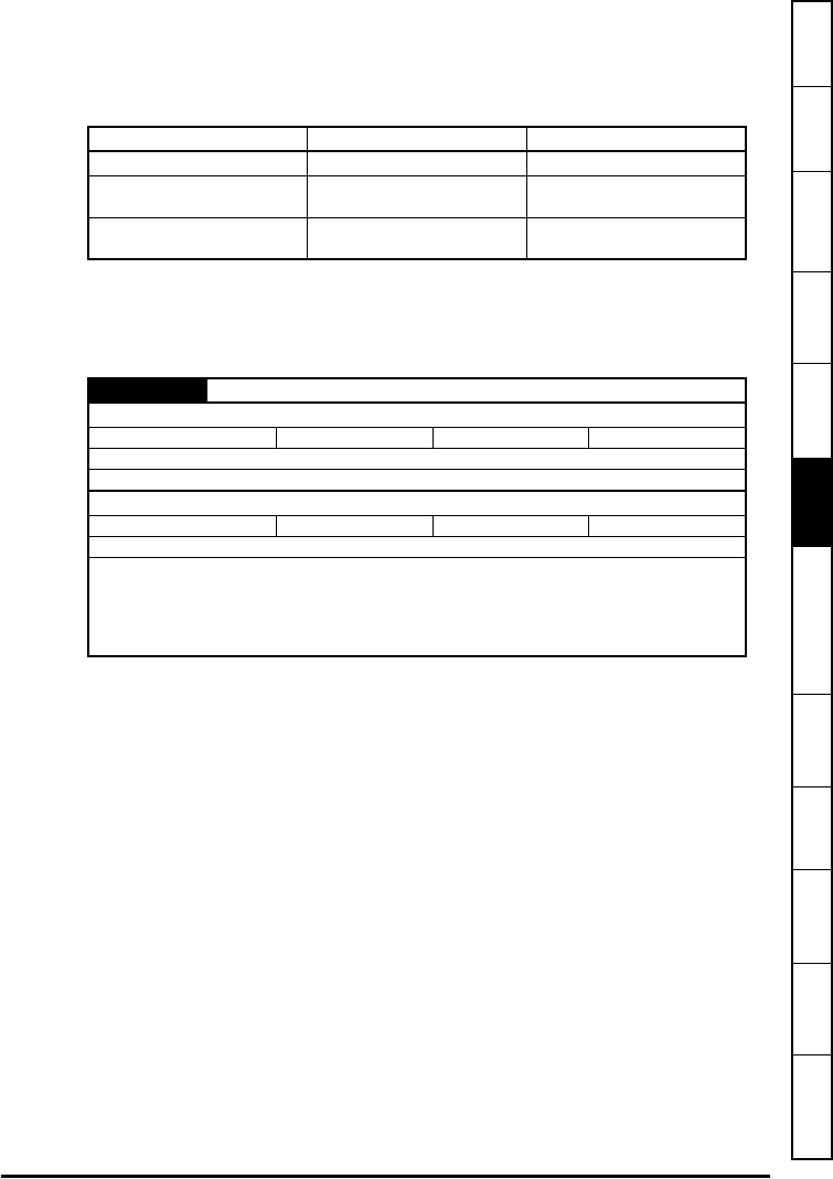
Table 6.7 RxPDO mapping 1
0x1600 Receive PDO mapping 1
Sub-index 0: Number of mapped objects
Access: RW Range: 0 to (CF) Size: 1 byte Unit: N/A
Default: 1
Description: The number of mapped objects in thie PDO
Sub-index 1: 1st mapped object
Access: RW Range: 0 to 0xFFFFFFFF Size: 4 bytes Unit: N/A
Default: 0x60400010 - the DSP-402 control word (0x6040)
Description: A mapping to an object with the following format:
Bits 0 to 7: Length of the mapped object in bits, e.g. a 32-bit parameter would have a length
of 32 or 0x20.
Bits 8 to 15: Sub-index of the mapped object.
Bits 16 to 31: Index of the mapped object.