
Switch User Manual
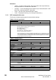
Table Of Contents
- Contents
- 1 Safety Information
- 2 Introduction
- 3 Mechanical Installation
- 4 Electrical Installation
- 5 Getting Started
- 6 Protocols
- 7 Drive profile (DSP-402) support
- 7.1 0x6040 Controlword
- 7.2 0x6041 Statusword
- 7.3 Common profile features
- 7.3.1 Sequencing control
- 7.3.2 0x605A Quick stop option code
- 7.3.3 0x605B Shutdown_option_code
- 7.3.4 0x605C Disable_operation_option_code
- 7.3.5 0x605E Fault_reaction_option_code
- 7.3.6 0x6060 Modes_of_operation
- 7.3.7 0x6061 Modes_of_operation_display
- 7.3.8 0x6085 Quick_stop_deceleration
- 7.3.9 Profile units
- 7.3.10 0x608F Position_encoder_resolution
- 7.3.11 0x6091 Gear_ratio
- 7.3.12 0x6092 Feed_constant
- 7.3.13 Basic position control
- 7.3.14 0x6062 Position_demand_value
- 7.3.15 0x6064 Position_actual_value
- 7.3.16 0x60F4 Following_error_actual_value
- 7.3.17 0x60FB Position_control_parameter_set object
- 7.4 Interpolated position mode
- 7.5 vl velocity mode
- 7.5.1 0x6042 vl_target_velocity
- 7.5.2 0x6043 vl_velocity_demand
- 7.5.3 0x6044 vl_velocity_actual_value
- 7.5.4 0x6046 vl_velocity_min_max_amount
- 7.5.5 0x6047 vl_velocity_min_max
- 7.5.6 0x6048 vl_velocity_acceleration
- 7.5.7 0x6049 vl_velocity_deceleration
- 7.5.8 0x604A vl_velocity_quick_stop
- 7.5.9 0x604B vl_setpoint_factor
- 7.5.10 0x604C vl_dimension_factor
- 7.6 Profile Torque mode
- 7.7 Homing Mode
- 8 Advanced features
- 9 Diagnostics
- 9.1 Module identification parameters
- 9.2 Network configuration objects
- 9.3 Diagnostic parameters
- 9.4 Drive trip display codes
- 9.5 SM-EtherCAT module temperature
- 9.6 SM-EtherCAT serial number
- 9.7 SM-EtherCAT error codes
- 9.8 Critical task % free
- 9.9 Worst case critical task % free
- 9.10 FLASH file system % free
- 9.11 Updating SM-EtherCAT firmware
- 10 Quick Reference
- 11 Glossary Of Terms
- Index
20 SM-EtherCAT User Guide
www.controltechniques.com Issue Number: 2
Definitions:
• <index> : A signed 16-bit number. This is the index of the object dictionary
entry specified in four hexadecimal characters.
• <access> : A value describing how the object may be accessed (RW = read/
write, RO = read-only and WO = write-only).
• <size> : The size of the object/sub-index in bytes.
• <unit> : The physical unit (e.g. ms, counts per second etc.).
6.1.1 CoE communication area
The first set of objects specify general communication settings.
Table 6.4 Device type object
0x1000 Device type
Access: RO Range: N/A Size: 4 bytes Unit: N/A
Default: 0x00030192
Description: The primary CoE functional profile is DSP-402, the value of the object is defined as follows:
Bits 0 to 15 (Device profile number): 402 (0x192)
Bit 16 (Frequency converter): x
Bit 17 (Servo drive): y
Bit 18 (Stepper motor): 0
Bit 24 (DC drive - manufacturer specific : z
Bits 25 to 31 (Manufacturer specific): 0
This value will depend on the drive operating mode and/or type. On a Unidrive SP in open-
loop or closed-loop mode or a Mentor MP in closed-loop mode, bit 16 will be set, while bits
17 and 24 will be cleared. On a Unidrive SP in Servo mode or a Digitax ST, bit 17 will be
set, while bits 16 and 24 will be cleared.
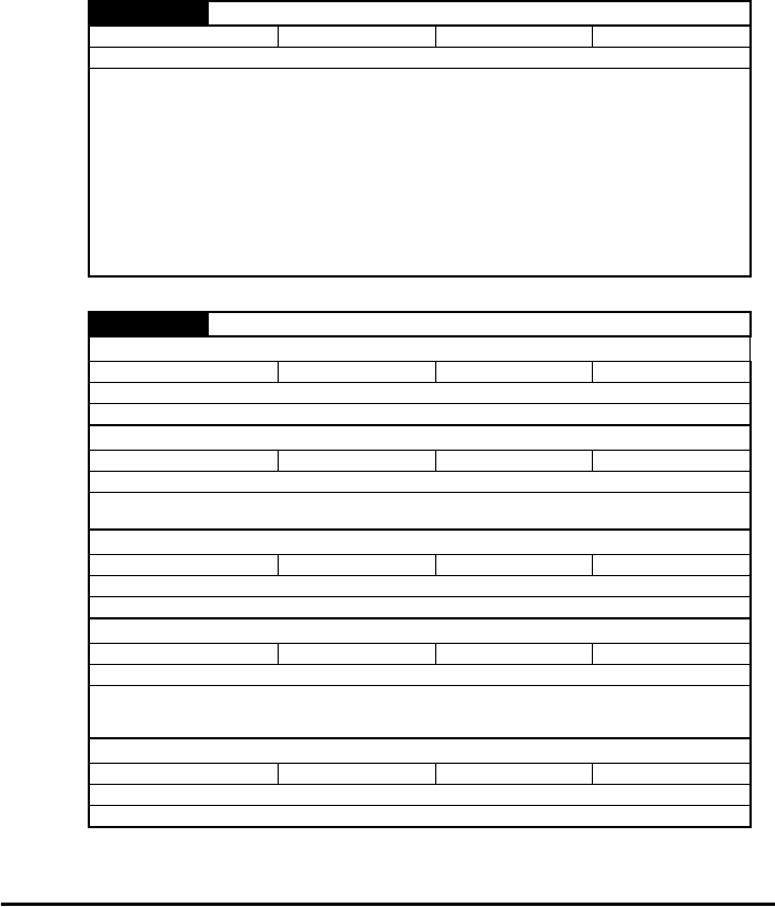
Table 6.5 Identity object
0x1018 Identity object
Sub-index 0
Access: RO Range: N/A Size: 1 byte Unit: N/A
Default: 4
Description: The number of the last sub-index in this object.
Sub-index 1
Access: RO Range: N/A Size: 4 bytes Unit: N/A
Default: 0x000000F9
Description: This contains the EtherCAT Technology Group vendor ID for Control Techniques
(0x000000F9).
Sub-index 2
Access: RO Range: N/A Size: 4 bytes Unit: N/A
Default: See Pr MM.01.
Description: This has the value of the option ID code.
Sub-index 3
Access: RO Range: N/A Size: 4 bytes Unit: N/A
Default: High word: Pr MM.02. Low word: Pr MM.51.
Description: Contains the option module software version number (the major and minor version
parameter are placed in the high word of this object, and the sub-version parameter is the
low word).
Sub-index 4
Access: RO Range: N/A Size: 4 bytes Unit: N/A
Default: See Pr MM.35.
Description: Contains the option hardware serial number.