
Switch User Manual
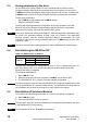
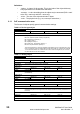
Table Of Contents
- Contents
- 1 Safety Information
- 2 Introduction
- 3 Mechanical Installation
- 4 Electrical Installation
- 5 Getting Started
- 6 Protocols
- 7 Drive profile (DSP-402) support
- 7.1 0x6040 Controlword
- 7.2 0x6041 Statusword
- 7.3 Common profile features
- 7.3.1 Sequencing control
- 7.3.2 0x605A Quick stop option code
- 7.3.3 0x605B Shutdown_option_code
- 7.3.4 0x605C Disable_operation_option_code
- 7.3.5 0x605E Fault_reaction_option_code
- 7.3.6 0x6060 Modes_of_operation
- 7.3.7 0x6061 Modes_of_operation_display
- 7.3.8 0x6085 Quick_stop_deceleration
- 7.3.9 Profile units
- 7.3.10 0x608F Position_encoder_resolution
- 7.3.11 0x6091 Gear_ratio
- 7.3.12 0x6092 Feed_constant
- 7.3.13 Basic position control
- 7.3.14 0x6062 Position_demand_value
- 7.3.15 0x6064 Position_actual_value
- 7.3.16 0x60F4 Following_error_actual_value
- 7.3.17 0x60FB Position_control_parameter_set object
- 7.4 Interpolated position mode
- 7.5 vl velocity mode
- 7.5.1 0x6042 vl_target_velocity
- 7.5.2 0x6043 vl_velocity_demand
- 7.5.3 0x6044 vl_velocity_actual_value
- 7.5.4 0x6046 vl_velocity_min_max_amount
- 7.5.5 0x6047 vl_velocity_min_max
- 7.5.6 0x6048 vl_velocity_acceleration
- 7.5.7 0x6049 vl_velocity_deceleration
- 7.5.8 0x604A vl_velocity_quick_stop
- 7.5.9 0x604B vl_setpoint_factor
- 7.5.10 0x604C vl_dimension_factor
- 7.6 Profile Torque mode
- 7.7 Homing Mode
- 8 Advanced features
- 9 Diagnostics
- 9.1 Module identification parameters
- 9.2 Network configuration objects
- 9.3 Diagnostic parameters
- 9.4 Drive trip display codes
- 9.5 SM-EtherCAT module temperature
- 9.6 SM-EtherCAT serial number
- 9.7 SM-EtherCAT error codes
- 9.8 Critical task % free
- 9.9 Worst case critical task % free
- 9.10 FLASH file system % free
- 9.11 Updating SM-EtherCAT firmware
- 10 Quick Reference
- 11 Glossary Of Terms
- Index

16 SM-EtherCAT User Guide
www.controltechniques.com Issue Number: 2
Assigning RxPDO to the Sync Manager
To assign RxPDO1 to sync manager 2 PDO assignment set the values below to the
following objects:
• Index: 0x1C12
• Sub index: 0x00
•Size: 1
• Value: 1
Setting object 0x1C12, sub-index 0 to a value of 1 (as above) indicates that one RxPDO
will be assigned to the sync manager 2 assignment.
• Index: 0x1C12
• Sub index: 0x01
•Size: 2
• Value: 0x1600
Setting object 0x1C12, sub-index 1 to a value of 0x1600 (as above) maps RxPDO1 to
the process data output sync.
Assigning TxPDO to the Sync Manager
To assign TxPDO1 to sync manager 3 PDO assignment set the values below to the
following objects:
• Index: 0x1C13
• Sub index: 0x00
•Size: 1
• Value: 2
Setting object 0x1C13, sub-index 0 to a value of 2 (as above) indicates that two
TxPDO's will be assigned to the sync manager 3 assignment.
• Index: 0x1C13
• Sub index: 0x01
•Size: 2
• Value: 0x1A00
• Index: 0x1C13
• Sub index: 0x02
•Size: 2
• Value: 0x1A05
Setting object 0x1C13, sub-index 1 to a value of 0x1A00 and sub-index 2 to a value of
0x1A05 (as above) maps TxPDO1 and TxPDO6 to the process data input sync.
Download the configuration to the master.
After downloading the configuration to the master the LED(s) on the front of the SM-
EtherCAT should flash, depending on the port(s) connected.
Values written to parameters over RxPDOs should now be viewable using the drive’s
keypad so long as the master has put the slave into the Operational state; also,
parameter values changed using the drive keypad will be updated on the master.