
Switch User Manual
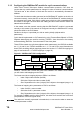
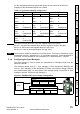
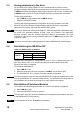
Table Of Contents
- Contents
- 1 Safety Information
- 2 Introduction
- 3 Mechanical Installation
- 4 Electrical Installation
- 5 Getting Started
- 6 Protocols
- 7 Drive profile (DSP-402) support
- 7.1 0x6040 Controlword
- 7.2 0x6041 Statusword
- 7.3 Common profile features
- 7.3.1 Sequencing control
- 7.3.2 0x605A Quick stop option code
- 7.3.3 0x605B Shutdown_option_code
- 7.3.4 0x605C Disable_operation_option_code
- 7.3.5 0x605E Fault_reaction_option_code
- 7.3.6 0x6060 Modes_of_operation
- 7.3.7 0x6061 Modes_of_operation_display
- 7.3.8 0x6085 Quick_stop_deceleration
- 7.3.9 Profile units
- 7.3.10 0x608F Position_encoder_resolution
- 7.3.11 0x6091 Gear_ratio
- 7.3.12 0x6092 Feed_constant
- 7.3.13 Basic position control
- 7.3.14 0x6062 Position_demand_value
- 7.3.15 0x6064 Position_actual_value
- 7.3.16 0x60F4 Following_error_actual_value
- 7.3.17 0x60FB Position_control_parameter_set object
- 7.4 Interpolated position mode
- 7.5 vl velocity mode
- 7.5.1 0x6042 vl_target_velocity
- 7.5.2 0x6043 vl_velocity_demand
- 7.5.3 0x6044 vl_velocity_actual_value
- 7.5.4 0x6046 vl_velocity_min_max_amount
- 7.5.5 0x6047 vl_velocity_min_max
- 7.5.6 0x6048 vl_velocity_acceleration
- 7.5.7 0x6049 vl_velocity_deceleration
- 7.5.8 0x604A vl_velocity_quick_stop
- 7.5.9 0x604B vl_setpoint_factor
- 7.5.10 0x604C vl_dimension_factor
- 7.6 Profile Torque mode
- 7.7 Homing Mode
- 8 Advanced features
- 9 Diagnostics
- 9.1 Module identification parameters
- 9.2 Network configuration objects
- 9.3 Diagnostic parameters
- 9.4 Drive trip display codes
- 9.5 SM-EtherCAT module temperature
- 9.6 SM-EtherCAT serial number
- 9.7 SM-EtherCAT error codes
- 9.8 Critical task % free
- 9.9 Worst case critical task % free
- 9.10 FLASH file system % free
- 9.11 Updating SM-EtherCAT firmware
- 10 Quick Reference
- 11 Glossary Of Terms
- Index
SM-EtherCAT User Guide 15
Issue Number: 2 www.controltechniques.com
Safety
Information
Introduction
Mechanical
Installation
Electrical
Installation
Getting
Started
Protocols
Drive profile (DSP-402)
support
Advanced
features
Diagnostics
Quick
Reference
Glossary Of
Terms
Index
For this example the following objects will need to be set in order to achieve the
mappings of the parameters/objects in the PDOs.
5.1.4 Configuring the Sync Managers
The Sync manager is used to control the transmission of CANopen PDOs over the
EtherCAT network.
The following objects 0x1C12 - Sync manager 2 PDO assignment (RxPDO) and
0x1C13 - Sync manager 3 PDO assignment (TxPDO) are required to assign PDOs to
the synchronization task. For the purpose of the example assign one RxPDO to sync
manager 2 and two TxPDOs to sync manager 3.
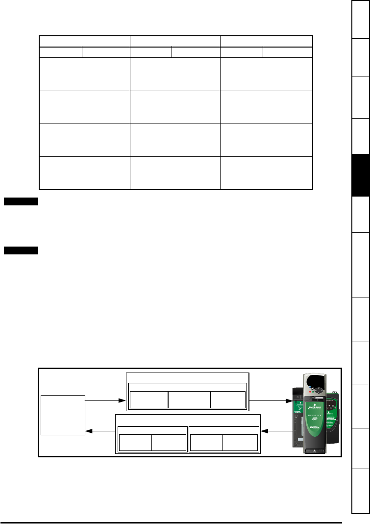
Figure 5-2 SM-EtherCAT sync manager configuration
Table 5.3 Cyclic data mapping configuration
RxPDO1: TxPDO1: TxPDO6:
Object: 0x1600 Object: 0x1A00 Object: 0x1A05
Sub-index: 0x00 Sub-index: 0x00 Sub-index: 0x00
Size: 1 Size: 1 Size: 1
Value: 3 Value: 2 Value: 2
Sub-index: 0x01 Sub-index: 0x01 Sub-index: 0x01
Size: 4 Size: 4 Size: 4
Value: 0x60400010 Value: 0x60410010 Value: 0x20121610
Sub-index: 0x02 Sub-index: 0x02 Sub-index: 0x02
Size: 4 Size: 4 Size: 4
Value: 0x60420010 Value: 0x60640020 Value: 0x20141620
Sub-index: 0x03
Not Used Not Used
Size: 4
Value: 0x20141520
The format used to define the value of a mapped object is as follows:
Bit 0 to 7: Length of the mapped object in bits (if a gap, bit length of the gap).
Bit 8 to 15: Sub-index of the mapped object (if a gap, zero).
Bit 16 to 31: Index of the mapped object (if a gap, zero).
The maximum number of mappings in one PDO is five. There are no restrictions on the
data length of these 5 parameters (i.e. It is possible to map five, 32-bit parameters in
one PDO). It is also possible to use a maximum of 2 x RxPDOs and 2 x TxPDOs.
NOTE
NOTE
0x1C12
0x6040
Control word
0x6042
vl_target_velocity
Pr 20.21
RxPDO1
0x1C13
0x6041
Status word
0x6064
position
actual value
TxPDO1
Pr 18.22 Pr 20.22
TxPDO6
PLC