
Switch User Manual
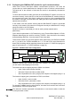
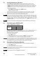
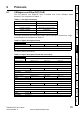
Table Of Contents
- Contents
- 1 Safety Information
- 2 Introduction
- 3 Mechanical Installation
- 4 Electrical Installation
- 5 Getting Started
- 6 Protocols
- 7 Drive profile (DSP-402) support
- 7.1 0x6040 Controlword
- 7.2 0x6041 Statusword
- 7.3 Common profile features
- 7.3.1 Sequencing control
- 7.3.2 0x605A Quick stop option code
- 7.3.3 0x605B Shutdown_option_code
- 7.3.4 0x605C Disable_operation_option_code
- 7.3.5 0x605E Fault_reaction_option_code
- 7.3.6 0x6060 Modes_of_operation
- 7.3.7 0x6061 Modes_of_operation_display
- 7.3.8 0x6085 Quick_stop_deceleration
- 7.3.9 Profile units
- 7.3.10 0x608F Position_encoder_resolution
- 7.3.11 0x6091 Gear_ratio
- 7.3.12 0x6092 Feed_constant
- 7.3.13 Basic position control
- 7.3.14 0x6062 Position_demand_value
- 7.3.15 0x6064 Position_actual_value
- 7.3.16 0x60F4 Following_error_actual_value
- 7.3.17 0x60FB Position_control_parameter_set object
- 7.4 Interpolated position mode
- 7.5 vl velocity mode
- 7.5.1 0x6042 vl_target_velocity
- 7.5.2 0x6043 vl_velocity_demand
- 7.5.3 0x6044 vl_velocity_actual_value
- 7.5.4 0x6046 vl_velocity_min_max_amount
- 7.5.5 0x6047 vl_velocity_min_max
- 7.5.6 0x6048 vl_velocity_acceleration
- 7.5.7 0x6049 vl_velocity_deceleration
- 7.5.8 0x604A vl_velocity_quick_stop
- 7.5.9 0x604B vl_setpoint_factor
- 7.5.10 0x604C vl_dimension_factor
- 7.6 Profile Torque mode
- 7.7 Homing Mode
- 8 Advanced features
- 9 Diagnostics
- 9.1 Module identification parameters
- 9.2 Network configuration objects
- 9.3 Diagnostic parameters
- 9.4 Drive trip display codes
- 9.5 SM-EtherCAT module temperature
- 9.6 SM-EtherCAT serial number
- 9.7 SM-EtherCAT error codes
- 9.8 Critical task % free
- 9.9 Worst case critical task % free
- 9.10 FLASH file system % free
- 9.11 Updating SM-EtherCAT firmware
- 10 Quick Reference
- 11 Glossary Of Terms
- Index
14 SM-EtherCAT User Guide
www.controltechniques.com Issue Number: 2
5.1.3 Configuring the SM-EtherCAT module for cyclic communications
Unlike other Control Techniques fieldbus communication protocols, CoE does not
require that any module parameters be changed in order to achieve communications.
The baud rate of the network is fixed and the module is automatically allocated an
address.
To check that the ethernet cable connected to the SM-EtherCAT module on the drive is
connected correctly, look at the LED on the front of the SM-EtherCAT module relating to
the connector being used, if this light is a solid green color then a link is established with
the master, if this light if off then check the cabling and also check that the master has
started communications.
In the master, scan the network ensuring that the SM-EtherCAT module is connected
correctly to the master. If the network is configured correctly the SM-EtherCAT node(s)
should be visible in the PLC Master.
Decide on the input / output data you wish to send cyclically (objects and/or
parameters).
Cyclic data is implemented on CoE networks by using "Process Data Objects" or PDOs.
Separate data objects are used for receiving (TxPDOs - from the slave to the master)
and transmitting (RxPDOs - from the master to the slave) data.
These PDOs contain the cyclic data (objects and/or parameters), the RxPDOs available
are 1, 2, 6 and 22, the TxPDOs available are 1, 2, 3, 6 and 22 (for more information on
these PDOs including default mappings please see
section 6.1.2 RxPDO mappings on
page 21 and section 6.1.3 TxPDO mappings on page 23).
Figure 5-1 SM-EtherCAT PDO configuration
RxPDO1, TxPDO1 and TxPDO6 will need to be enabled in the master. Once enabled
you will need to add mappings to the PDOs.
The format used when mapping objects to PDOs is as follows:
• Index: Object index number (0x0000)
• Sub-index: Object sub-index number (0x00)
• Size: Dependant on the size (in bytes) of the object to be mapped (range: 1-4)
The format of mapping drive parameters to PDO is as follows:
• Index: 0x2000 + menu number
• Sub-index: 0x00 + parameter number
• Size: Dependant on the size (in bytes) of the object to be mapped (range: 1-4)
For example Pr 20.21 would be index 0x2014, sub-index 0x15 and the size would be 4
(the parameter is a 32-bit signed value).
The values are normally expressed in hexadecimal, so care must be taken to enter the
correct parameter number.
NOTE
0x6041
Status word
0x6064 position
actual value
TxPDO1
Pr 18.22 Pr 20.22
TxPDO6
PLC
0x6040
Control word
0x6042
vl_target_velocity
Pr 20.21
RxPDO1