
Switch User Manual
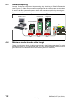
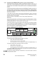
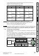
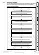
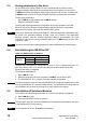
Table Of Contents
- Contents
- 1 Safety Information
- 2 Introduction
- 3 Mechanical Installation
- 4 Electrical Installation
- 5 Getting Started
- 6 Protocols
- 7 Drive profile (DSP-402) support
- 7.1 0x6040 Controlword
- 7.2 0x6041 Statusword
- 7.3 Common profile features
- 7.3.1 Sequencing control
- 7.3.2 0x605A Quick stop option code
- 7.3.3 0x605B Shutdown_option_code
- 7.3.4 0x605C Disable_operation_option_code
- 7.3.5 0x605E Fault_reaction_option_code
- 7.3.6 0x6060 Modes_of_operation
- 7.3.7 0x6061 Modes_of_operation_display
- 7.3.8 0x6085 Quick_stop_deceleration
- 7.3.9 Profile units
- 7.3.10 0x608F Position_encoder_resolution
- 7.3.11 0x6091 Gear_ratio
- 7.3.12 0x6092 Feed_constant
- 7.3.13 Basic position control
- 7.3.14 0x6062 Position_demand_value
- 7.3.15 0x6064 Position_actual_value
- 7.3.16 0x60F4 Following_error_actual_value
- 7.3.17 0x60FB Position_control_parameter_set object
- 7.4 Interpolated position mode
- 7.5 vl velocity mode
- 7.5.1 0x6042 vl_target_velocity
- 7.5.2 0x6043 vl_velocity_demand
- 7.5.3 0x6044 vl_velocity_actual_value
- 7.5.4 0x6046 vl_velocity_min_max_amount
- 7.5.5 0x6047 vl_velocity_min_max
- 7.5.6 0x6048 vl_velocity_acceleration
- 7.5.7 0x6049 vl_velocity_deceleration
- 7.5.8 0x604A vl_velocity_quick_stop
- 7.5.9 0x604B vl_setpoint_factor
- 7.5.10 0x604C vl_dimension_factor
- 7.6 Profile Torque mode
- 7.7 Homing Mode
- 8 Advanced features
- 9 Diagnostics
- 9.1 Module identification parameters
- 9.2 Network configuration objects
- 9.3 Diagnostic parameters
- 9.4 Drive trip display codes
- 9.5 SM-EtherCAT module temperature
- 9.6 SM-EtherCAT serial number
- 9.7 SM-EtherCAT error codes
- 9.8 Critical task % free
- 9.9 Worst case critical task % free
- 9.10 FLASH file system % free
- 9.11 Updating SM-EtherCAT firmware
- 10 Quick Reference
- 11 Glossary Of Terms
- Index
SM-EtherCAT User Guide 11
Issue Number: 2 www.controltechniques.com
Safety
Information
Introduction
Mechanical
Installation
Electrical
Installation
Getting
Started
Protocols
Drive profile (DSP-402)
support
Advanced
features
Diagnostics
Quick
Reference
Glossary Of
Terms
Index
4 Electrical Installation
4.1 SM-EtherCAT module information
4.1.1 Bus media
The SM-EtherCAT option module incorporates two x 100 BASE-TX RJ45 interfaces.
4.1.2 Cabling considerations
To ensure long-term reliability it is recommended that any cables used to connect a
system together be tested using a suitable Ethernet cable tester, this is of particular
importance when cables are constructed on site.
4.1.3 Cable
Cables should be shielded and as a minimum, meet TIA Cat 5e requirements.
4.1.4 Maximum network length
The main restriction imposed on Ethernet cabling is the length of a single segment of
cable. The SM-EtherCAT module has two 100BASE-TX Ethernet ports, which support
segment lengths of up to 100m. This means that the maximum cable length which can
be used between one SM-EtherCAT port and another 100BASE-TX port is 100m
however it is not recommended that the full 100m cable length is used. The total
network length is not restricted by the Ethernet standard but depends on the number of
devices on the network and the transmission media (copper, fiber optic, etc.).
4.2 Module grounding
SM-EtherCAT is supplied with a grounding tag on the module that should be connected
to the closest possible grounding point using the minimum length of cable. This will
greatly improve the noise immunity of the module.
Cabling issues are the single biggest cause of network downtime. Ensure cabling is
correctly routed, wiring is correct, connectors are correctly fitted and any switches or
routers used are rated for industrial use. Office grade Ethernet equipment does not
generally offer the same degree of noise immunity as equipment intended for industrial
use.
NOTE
The EtherCAT system designer must consider the impact that the selected network
structure will have on performance.
NOTE