
Network Router User Manual


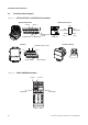
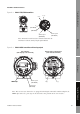
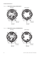
Table Of Contents
- Contents
- Before You Begin
- Installation and Setup
- 2.1 Overview
- 2.2 Installation and setup
- 2.2.1 Ensure required privileges
- 2.2.2 Install the ProLink II software
- 2.2.3 Generate the temporary license
- 2.2.4 Determine your connection type
- 2.2.5 Install the signal converter and connect the wires
- 2.2.6 Configure ProLink II connection parameters and connect to the transmitter
- 2.2.7 Obtain and configure a site key
- 2.3 Troubleshooting the ProLink II installation
- 2.4 Troubleshooting the ProLink II connection
- Using ProLink II Software
- Initial Transmitter Startup Procedures
- Transmitter Configuration, Characterization, and Calibration
- Meter Verification
- Data Logger
- Transmitter Terminal Reference
- Configuring the Discrete Batch Application
- Index
Installation and Use Manual 83
Transmitter Terminal Reference
Meter Verification Transmitter TerminalsData LoggerTransmitter Configuration
Figure A-3 Model 1700/2700 transmitters
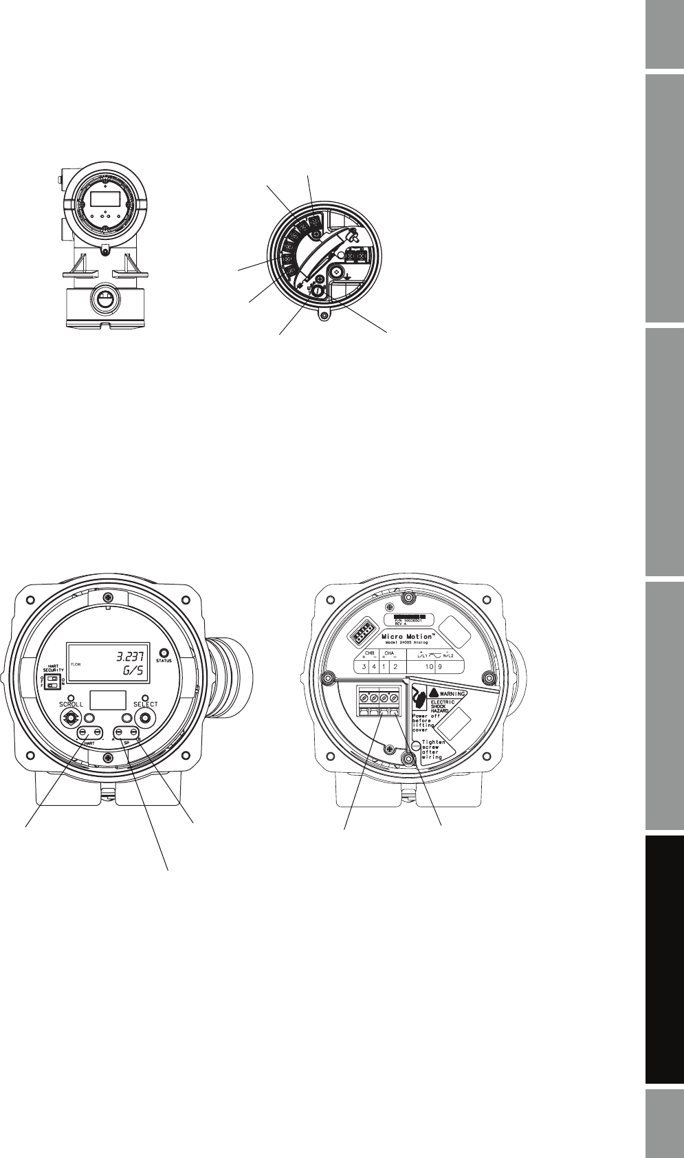
Figure A-4 Model 2400S transmitters with analog outputs
1 (+)
2 (–)
5
(RS-485/A)
6
(RS-485/B)
8
Service port
(RS-485/A)
7
Service port
(RS-485/B)
Note: Terminals 5 and 6 used for communications only by
transmitters with the analog outputs option board.
User interface
(with display, cover removed)
Outputs wiring compartment
(user interface removed)
HART clips
HART clips
1 (+)
2 (–)
Service port
(RS-485/B)
Service port
(RS-485/A)
Note: The user interface shown here is equipped with a display. On models without a display, the
HART clips and service port clips are located in the same position on the user interface.