
Network Router User Manual

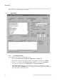

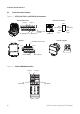
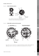
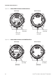
Table Of Contents
- Contents
- Before You Begin
- Installation and Setup
- 2.1 Overview
- 2.2 Installation and setup
- 2.2.1 Ensure required privileges
- 2.2.2 Install the ProLink II software
- 2.2.3 Generate the temporary license
- 2.2.4 Determine your connection type
- 2.2.5 Install the signal converter and connect the wires
- 2.2.6 Configure ProLink II connection parameters and connect to the transmitter
- 2.2.7 Obtain and configure a site key
- 2.3 Troubleshooting the ProLink II installation
- 2.4 Troubleshooting the ProLink II connection
- Using ProLink II Software
- Initial Transmitter Startup Procedures
- Transmitter Configuration, Characterization, and Calibration
- Meter Verification
- Data Logger
- Transmitter Terminal Reference
- Configuring the Discrete Batch Application
- Index
82 ProLink
®
II Software for Micro Motion
®
Transmitters
Transmitter Terminal Reference
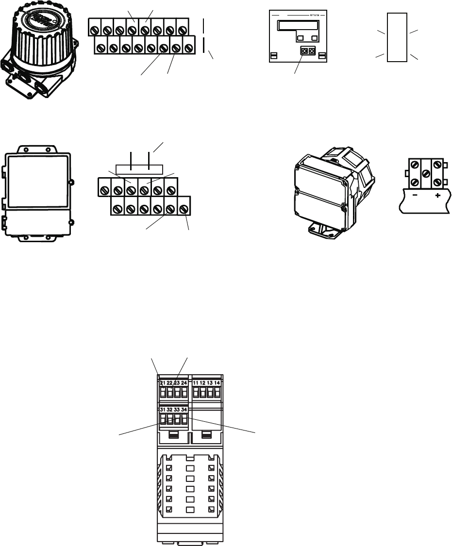
A.2 Transmitter terminal diagrams
Figure A-1 RFT9739, RFT9712, and IFT9701/9793 transmitters
Figure A-2 Model 1500/2500 transmitters
17 (+) 16 (–)
RFT9712
RFT9739 field-mount
17 (PV+) 18 (PV –)
D30
(PV–)
CN2
RFT9739 rack-mount
IFT9701 / IFT9703
HART jack
27 (RS-485/A)26 (RS-485/B)
D22
(RS-485/A)
Z22
(RS-485/B
)
Z30
(PV+)
22 (RS-485/B) 21 (RS-485/A)
HART/Bell-202 hookups
HART/Bell-202
hookups
4–20mA
21 (PV+) 22 (PV–)
33
(RS-485/A)
34
(RS-485/B)