
Network Router User Manual
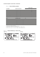
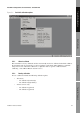

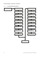
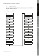
Table Of Contents
- Contents
- Before You Begin
- Installation and Setup
- 2.1 Overview
- 2.2 Installation and setup
- 2.2.1 Ensure required privileges
- 2.2.2 Install the ProLink II software
- 2.2.3 Generate the temporary license
- 2.2.4 Determine your connection type
- 2.2.5 Install the signal converter and connect the wires
- 2.2.6 Configure ProLink II connection parameters and connect to the transmitter
- 2.2.7 Obtain and configure a site key
- 2.3 Troubleshooting the ProLink II installation
- 2.4 Troubleshooting the ProLink II connection
- Using ProLink II Software
- Initial Transmitter Startup Procedures
- Transmitter Configuration, Characterization, and Calibration
- Meter Verification
- Data Logger
- Transmitter Terminal Reference
- Configuring the Discrete Batch Application
- Index
Installation and Use Manual 61
Transmitter Configuration, Characterization, and Calibration
Meter Verification Transmitter TerminalsData LoggerTransmitter Configuration
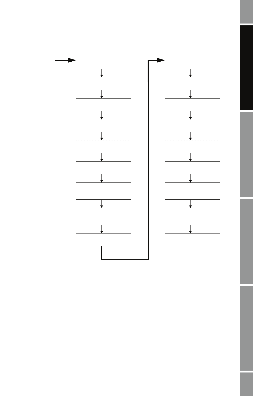
Figure 5-5 D1 and D2 density calibration
Fill sensor with D1 fluid
Calibration
Density cal - Point 1
Do Cal
Enter density of D1 fluid
Fill sensor with D2 fluid
Calibration in Progress
light turns red
ProLink
Calibration in Progress
light turns green
Calibration
Density cal - Point 2
Do Cal
Enter density of D2 fluid
Calibration in Progress
light turns red
ProLink
Calibration in Progress
light turns green
Close shutoff valve
downstream from sensor
Close Close