
Network Router User Manual
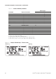
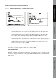
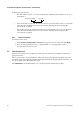
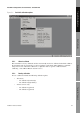
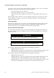

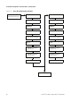
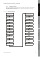
Table Of Contents
- Contents
- Before You Begin
- Installation and Setup
- 2.1 Overview
- 2.2 Installation and setup
- 2.2.1 Ensure required privileges
- 2.2.2 Install the ProLink II software
- 2.2.3 Generate the temporary license
- 2.2.4 Determine your connection type
- 2.2.5 Install the signal converter and connect the wires
- 2.2.6 Configure ProLink II connection parameters and connect to the transmitter
- 2.2.7 Obtain and configure a site key
- 2.3 Troubleshooting the ProLink II installation
- 2.4 Troubleshooting the ProLink II connection
- Using ProLink II Software
- Initial Transmitter Startup Procedures
- Transmitter Configuration, Characterization, and Calibration
- Meter Verification
- Data Logger
- Transmitter Terminal Reference
- Configuring the Discrete Batch Application
- Index
58 ProLink
®
II Software for Micro Motion
®
Transmitters
Transmitter Configuration, Characterization, and Calibration
To obtain the required value:
• For older T-Series sensors, concatenate the FCF value and the FT value from the sensor tag, as
shown below.
• For newer T-Series sensors, the 10-character string is represented on the sensor tag as the FCF
value. The value should be entered exactly as shown, including the decimal points. No
concatenation is required.
• For all other sensors, the 10-character string is represented on the sensor tag as the Flow Cal
value. The value should be entered exactly as shown, including the decimal points. No
concatenation is required.
5.4.3 How to characterize
To characterize the meter:
1. In the
ProLink > Configuration > Device panel, specify your sensor type and click Apply.
2. Set each of the required parameters, as listed in Table 5-1, to the appropriate value, as
described in the previous sections.
5.5 Calibrating the meter
The meter measures process variables based on fixed points of reference. Calibration adjusts those
points of reference.
This section provides a general method for calibration. For specific calibration information for your
transmitter, refer to the transmitter manual. Transmitter manuals are shipped with the transmitter, and
are also available on the Micro Motion web site.
The
Calibration menu, shown in Figure 5-4, is used to begin the calibration procedures.
Flow FCF X.XXXX FT X.XX