
Network Router User Manual
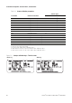
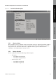

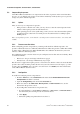
Table Of Contents
- Contents
- Before You Begin
- Installation and Setup
- 2.1 Overview
- 2.2 Installation and setup
- 2.2.1 Ensure required privileges
- 2.2.2 Install the ProLink II software
- 2.2.3 Generate the temporary license
- 2.2.4 Determine your connection type
- 2.2.5 Install the signal converter and connect the wires
- 2.2.6 Configure ProLink II connection parameters and connect to the transmitter
- 2.2.7 Obtain and configure a site key
- 2.3 Troubleshooting the ProLink II installation
- 2.4 Troubleshooting the ProLink II connection
- Using ProLink II Software
- Initial Transmitter Startup Procedures
- Transmitter Configuration, Characterization, and Calibration
- Meter Verification
- Data Logger
- Transmitter Terminal Reference
- Configuring the Discrete Batch Application
- Index
56 ProLink
®
II Software for Micro Motion
®
Transmitters
Transmitter Configuration, Characterization, and Calibration
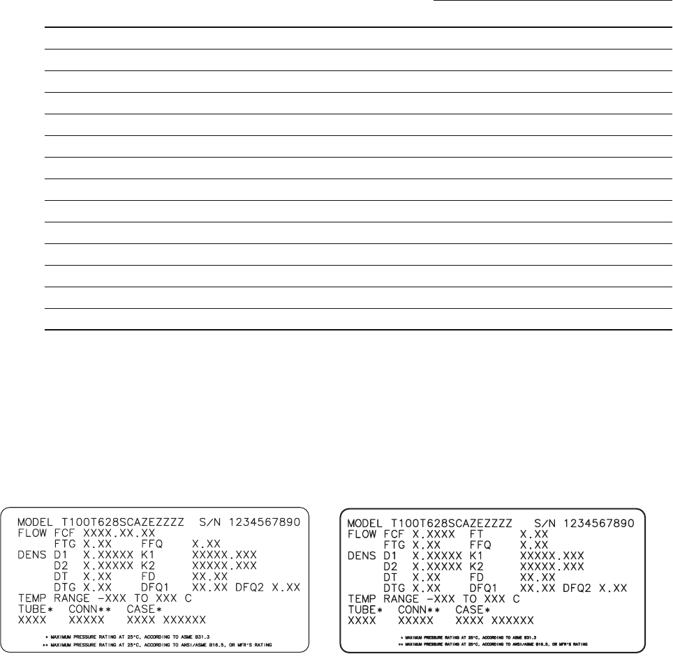
Figure 5-2 Sample calibration tags – T-Series sensor
Table 5-1 Sensor calibration parameters
Parameter ProLink II Location
Sensor type
T- S er ie s O t he r
K1 Configuration/Density ✓✓
(1)
(1) See the section entitled “Density calibration factors.”
K2 Configuration/Density ✓✓
(1)
FD Configuration/Density ✓✓
(1)
D1 Configuration/Density ✓✓
(1)
D2 Configuration/Density ✓✓
(1)
Temp coeff (DT)
(2)
(2) On some sensor tags, shown as TC.
Configuration/Density ✓✓
(1)
Flowcal Configuration/Flow ✓
(3)
(3) See the section entitled “Flow calibration values.”
FCF and FT Configuration/Flow ✓
(4)
(4) Older T-Series sensors. See the section entitled “Flow calibration values.”
FCF Configuration/Flow ✓
(5)
(5) Newer T-Series sensors. See the section entitled “Flow calibration values.”
FTG Configuration/T-Series Config ✓
FFQ Configuration/T-Series Config ✓
DTG Configuration/T-Series Config ✓
DFQ1 Configuration/T-Series Config ✓
DFQ2 Configuration/T-Series Config ✓
Newer tag Older tag