
Network Router User Manual
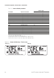
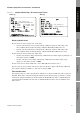
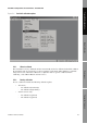

Table Of Contents
- Contents
- Before You Begin
- Installation and Setup
- 2.1 Overview
- 2.2 Installation and setup
- 2.2.1 Ensure required privileges
- 2.2.2 Install the ProLink II software
- 2.2.3 Generate the temporary license
- 2.2.4 Determine your connection type
- 2.2.5 Install the signal converter and connect the wires
- 2.2.6 Configure ProLink II connection parameters and connect to the transmitter
- 2.2.7 Obtain and configure a site key
- 2.3 Troubleshooting the ProLink II installation
- 2.4 Troubleshooting the ProLink II connection
- Using ProLink II Software
- Initial Transmitter Startup Procedures
- Transmitter Configuration, Characterization, and Calibration
- Meter Verification
- Data Logger
- Transmitter Terminal Reference
- Configuring the Discrete Batch Application
- Index

Installation and Use Manual 55
Transmitter Configuration, Characterization, and Calibration
Meter Verification Transmitter TerminalsData LoggerTransmitter Configuration
To use the Gas Unit Configurator:
1. Click the
Special Units tab, and click the Gas Unit Configurator button, or open the Tools
menu and click
Gas Unit Configurator.
2. Select the
Time Unit that your special unit will be based on.
3. Click a radio button to specify that your special unit will be defined in terms of
English Units
or
SI Units.
4. Click
Next.
5. Define the standard density to be used in calculations.
• To use a fixed standard density, click the top radio button, enter a value for standard
density in the
Standard Density textbox, and click Next.
• To use a calculated standard density, click the second radio button and click
Next. Then
enter values for
Reference Temperature, Reference Pressure, and Specific Gravity on
the next panel, and click
Next.
6. Check the values displayed.
• If they are appropriate for your application, click
Finish. The special unit data will be
written to the transmitter.
• If they are not appropriate for your application, click
Back as many times as necessary to
return to the relevant panel, correct the problem, then repeat the above steps.
5.4 Characterizing the meter
Characterizing the meter adjusts the transmitter to compensate for the unique traits of the sensor it is
paired with. The characterization parameters, or calibration parameters, describe the sensor’s
sensitivity to flow, density, and temperature.
5.4.1 When to characterize
If the transmitter and the sensor were ordered together as a Coriolis meter, then the meter has already
been characterized. You need to characterize the meter only if the transmitter and the sensor are being
paired together for the first time.
5.4.2 Characterization parameters
The characterization parameters that must be configured depend on your meter’s sensor type:
“T-Series” or “Other” (also referred to as “Straight Tube” and “Curved Tube,” respectively), as listed
in Table 5-1. The “Other” category includes all Micro Motion sensors except T-Series. Table 5-1 also
shows the location of each parameter within ProLink II.
The characterization parameters are provided on the sensor tag. The format of the sensor tag varies
depending on your sensor’s date of purchase. See Figures 5-2 and 5-3 for illustrations of newer and
older sensor tags.