
Network Router User Manual

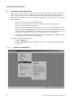
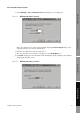
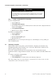
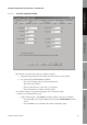
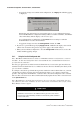
Table Of Contents
- Contents
- Before You Begin
- Installation and Setup
- 2.1 Overview
- 2.2 Installation and setup
- 2.2.1 Ensure required privileges
- 2.2.2 Install the ProLink II software
- 2.2.3 Generate the temporary license
- 2.2.4 Determine your connection type
- 2.2.5 Install the signal converter and connect the wires
- 2.2.6 Configure ProLink II connection parameters and connect to the transmitter
- 2.2.7 Obtain and configure a site key
- 2.3 Troubleshooting the ProLink II installation
- 2.4 Troubleshooting the ProLink II connection
- Using ProLink II Software
- Initial Transmitter Startup Procedures
- Transmitter Configuration, Characterization, and Calibration
- Meter Verification
- Data Logger
- Transmitter Terminal Reference
- Configuring the Discrete Batch Application
- Index
Installation and Use Manual 47
Initial Transmitter Startup Procedures
ProLink II Setup Transmitter StartupUsing ProLink IIBefore You Begin ProLink II Setup Transmitter StartupUsing ProLink IIBefore You Begin ProLink II Setup Transmitter StartupUsing ProLink IIBefore You Begin ProLink II Setup Transmitter StartupUsing ProLink IIBefore You Begin
3. Select Milliamp 1 Trim or Milliamp 2 Trim. The following screen is displayed:
Figure 4-4 Milliamp trim wizard – Screen 1
This screen allows you to compare the transmitter output (the
Present Output value) to the
output level being received at an external device.
4. Read the mA output level at the receiving device.
5. Type the value that you read at the receiving device in the
Enter Meas box.
6. Click
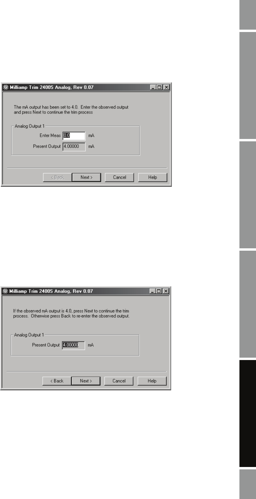
Next. At this point, the transmitter trims the milliamp output and displays the adjusted
output in the following screen:
Figure 4-5 Milliamp trim wizard – Screen 2