
Network Router User Manual
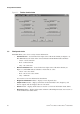


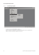
Table Of Contents
- Contents
- Before You Begin
- Installation and Setup
- 2.1 Overview
- 2.2 Installation and setup
- 2.2.1 Ensure required privileges
- 2.2.2 Install the ProLink II software
- 2.2.3 Generate the temporary license
- 2.2.4 Determine your connection type
- 2.2.5 Install the signal converter and connect the wires
- 2.2.6 Configure ProLink II connection parameters and connect to the transmitter
- 2.2.7 Obtain and configure a site key
- 2.3 Troubleshooting the ProLink II installation
- 2.4 Troubleshooting the ProLink II connection
- Using ProLink II Software
- Initial Transmitter Startup Procedures
- Transmitter Configuration, Characterization, and Calibration
- Meter Verification
- Data Logger
- Transmitter Terminal Reference
- Configuring the Discrete Batch Application
- Index

Installation and Use Manual 43
ProLink II Setup Transmitter StartupUsing ProLink IIBefore You Begin
Chapter 4
Initial Transmitter Startup Procedures
4.1 Overview
The procedures described in this chapter should be performed the first time a transmitter is started.
You can use ProLink II, the HART Communicator, AMS software, or the display to perform the
procedures: the communications method does not matter.
The following procedures are described:
• Using ProLink II to perform a loop test on transmitter outputs (and inputs, if your transmitter
has a discrete input or frequency input)
• Using ProLink II to trim the mA outputs
• Using ProLink II to zero the meter
Note: The procedures in this chapter provide general methods for using ProLink II with your
transmitter. For information on using the HART Communicator or the display, or for information
specific to your transmitter such as the number and type of outputs, specific ranges for each output,
etc., refer to the appropriate transmitter manual. Transmitter manuals are shipped with the
transmitter, and are also available on the Micro Motion web site.
Note: Sections 4.2 and 4.3 do not apply to Series 2000 transmitters with Profibus-PA or F
OUNDATION
fieldbus.
4.2 Loop tests
A loop test is a means to:
• Verify that outputs are being sent by the transmitter and received accurately by the receiving
devices
• Determine whether or not you need to trim the mA outputs
• Verify that the discrete input or frequency input sent by an external device is being received
correctly by the transmitter (if the transmitter has a discrete input or frequency input)
The ProLink II loop test options are shown in Figure 4-1. Different options are available with different
transmitters.