
Network Router User Manual
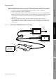
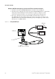
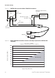
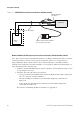
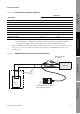
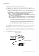
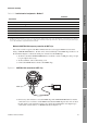
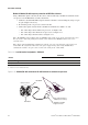
Table Of Contents
- Contents
- Before You Begin
- Installation and Setup
- 2.1 Overview
- 2.2 Installation and setup
- 2.2.1 Ensure required privileges
- 2.2.2 Install the ProLink II software
- 2.2.3 Generate the temporary license
- 2.2.4 Determine your connection type
- 2.2.5 Install the signal converter and connect the wires
- 2.2.6 Configure ProLink II connection parameters and connect to the transmitter
- 2.2.7 Obtain and configure a site key
- 2.3 Troubleshooting the ProLink II installation
- 2.4 Troubleshooting the ProLink II connection
- Using ProLink II Software
- Initial Transmitter Startup Procedures
- Transmitter Configuration, Characterization, and Calibration
- Meter Verification
- Data Logger
- Transmitter Terminal Reference
- Configuring the Discrete Batch Application
- Index

Installation and Use Manual 23
Installation and Setup
ProLink II Setup Transmitter StartupUsing ProLink IIBefore You Begin
Method 8: HART/Bell 202 temporary connection to HART clips
Note: This method is supported by Model 2400S transmitters that support HART communication.
Using a VIATOR HART Interface, the PC can be connected directly to the HART clips on the face of
the transmitter. Figure 2-9 shows the wiring for connection to the HART clips.
1. At the PC, attach the VIATOR HART Interface to the PC’s serial or USB port, using a 25-pin
to 9-pin adapter if necessary.
2. At the transmitter, remove the housing cover.
3. Connect the HART interface leads to the HART clips.
Figure 2-9 HART/Bell 202 connection to HART clips
4. If necessary, add a resistance across the HART clips. The VIATOR HART interface must be
connected across a resistance of 250–600 Ω. Note that the HART clips use the same circuit as
the mA output, so the required resistance may already be installed if the mA output loop is
connected to a remote device or a HART network (see Figure 2-1).
Table 2-11 Lead-to-terminal assignments – Method 7
Transmitter
Terminals
RS-485/A RS-485/B
Model 1500/2500 transmitters 33 34
All Model 1700/2700 transmitters 8 7
All Model 2400S transmitters
(1)
(1) On Model 2400S transmitters, service port connections are made via the service port clips which are located on the user interface.
Alternatively, service port connections are possible via the transmitter infrared port. For more information on using the infrared port,
refer to the transmitter configuration and use manual.
AB
Series 3000 panel-mount with screw-type connectors a32 c32
Series 3000 panel-mount with I/O cables 25 24
Series 3000 rack-mount a32 c32
Series 3000 field-mount 12 11
VIATOR
HART clips