
Network Router User Manual
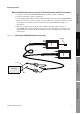
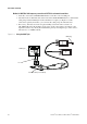
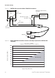
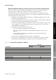
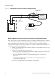
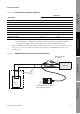
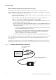
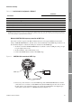
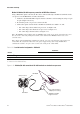
Table Of Contents
- Contents
- Before You Begin
- Installation and Setup
- 2.1 Overview
- 2.2 Installation and setup
- 2.2.1 Ensure required privileges
- 2.2.2 Install the ProLink II software
- 2.2.3 Generate the temporary license
- 2.2.4 Determine your connection type
- 2.2.5 Install the signal converter and connect the wires
- 2.2.6 Configure ProLink II connection parameters and connect to the transmitter
- 2.2.7 Obtain and configure a site key
- 2.3 Troubleshooting the ProLink II installation
- 2.4 Troubleshooting the ProLink II connection
- Using ProLink II Software
- Initial Transmitter Startup Procedures
- Transmitter Configuration, Characterization, and Calibration
- Meter Verification
- Data Logger
- Transmitter Terminal Reference
- Configuring the Discrete Batch Application
- Index

20 ProLink
®
II Software for Micro Motion
®
Transmitters
Installation and Setup
Figure 2-6 HART/RS-485 connection to transmitter or multidrop network
Method 6: Modbus/RS-485 temporary or hard-wired connection to RS-485 multidrop network
Note: This method is supported by RFT9739 transmitters, by Model 1500/2500 transmitters, by Model
1700/2700 transmitters with the analog outputs option board, and by Series 3000 transmitters.
Using a Black Box signal converter, the PC can be connected directly to a transmitter’s RS-485
terminals, to the output wires from these terminals, or to any point on an RS-485 network. Figure 2-7
shows the wiring for this connection type.
1. At the PC, attach the Black Box signal converter to the PC’s serial or USB port, using a 25-pin
to 9-pin adapter if necessary.
2. Attach the other end of the signal converter leads:
• To any point on the network (hard-wired connection). Ensure that the positive and negative
wires are connected as shown in Table 2-9.
• Directly to the RS-485 terminals on your transmitter (temporary connection). See
Table 2-10.
• To the output wires from the RS-485 terminals on your transmitter (hard-wired
connection). See Table 2-10.
For assistance in identifying the RS-485 terminals, see Appendix A.
DCS or
PLC
R1
See Step 5
BLACK
BOX
25-pin to 9-pin serial port adapter
(if necessary) (not shown)
RS-485 terminals
See Step 4
Transmitter