
Network Router User Manual
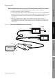
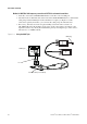
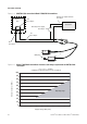
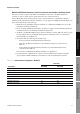
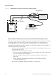
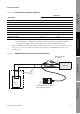
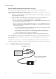
Table Of Contents
- Contents
- Before You Begin
- Installation and Setup
- 2.1 Overview
- 2.2 Installation and setup
- 2.2.1 Ensure required privileges
- 2.2.2 Install the ProLink II software
- 2.2.3 Generate the temporary license
- 2.2.4 Determine your connection type
- 2.2.5 Install the signal converter and connect the wires
- 2.2.6 Configure ProLink II connection parameters and connect to the transmitter
- 2.2.7 Obtain and configure a site key
- 2.3 Troubleshooting the ProLink II installation
- 2.4 Troubleshooting the ProLink II connection
- Using ProLink II Software
- Initial Transmitter Startup Procedures
- Transmitter Configuration, Characterization, and Calibration
- Meter Verification
- Data Logger
- Transmitter Terminal Reference
- Configuring the Discrete Batch Application
- Index
18 ProLink
®
II Software for Micro Motion
®
Transmitters
Installation and Setup
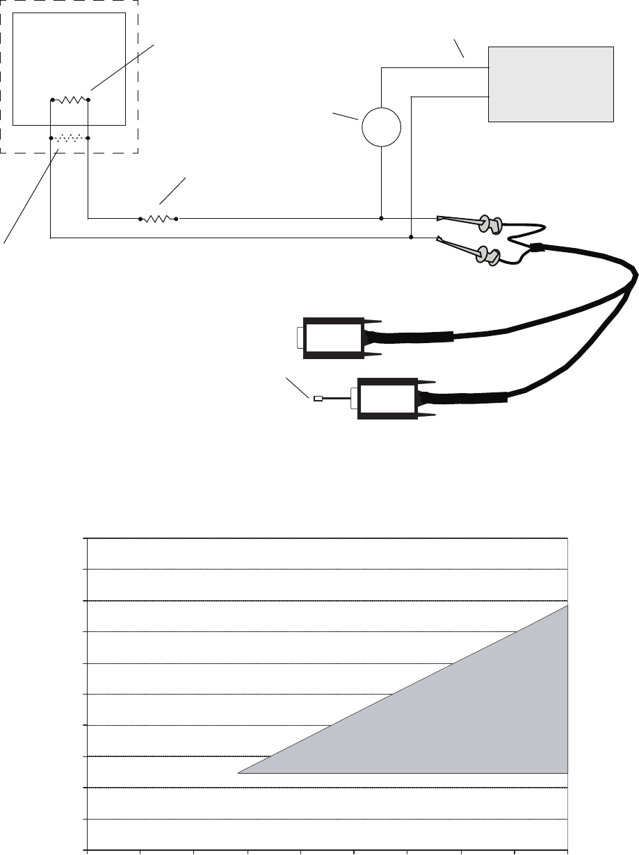
Figure 2-4 HART/Bell 202 connection to Model 1700/2700 IS transmitters
Figure 2-5 Model 1700/2700 IS transmitters: Resistance and voltage requirements for HART/Bell 202
connections
–
+
VIATOR
VIATOR
or
+
–
DCS or
PLC
R2
See Step 3
R3
See Step 3
R1
See Step 3
Primary mA output terminals
See Step 2
Transmitter
External power supply
See Step 3
USB plug
R
max
= (V
supply
– 12)/0.023
A minimum of 250 ohms and 17.5 volts is required
Supply voltage VDC (Volts)
External resistance (Ohms)
Operating range
12 3014 16 18 20 22 24 26 28
0
1000
900
800
700
600
500
400
300
200
100