
Network Router User Manual

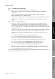
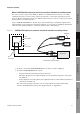
Table Of Contents
- Contents
- Before You Begin
- Installation and Setup
- 2.1 Overview
- 2.2 Installation and setup
- 2.2.1 Ensure required privileges
- 2.2.2 Install the ProLink II software
- 2.2.3 Generate the temporary license
- 2.2.4 Determine your connection type
- 2.2.5 Install the signal converter and connect the wires
- 2.2.6 Configure ProLink II connection parameters and connect to the transmitter
- 2.2.7 Obtain and configure a site key
- 2.3 Troubleshooting the ProLink II installation
- 2.4 Troubleshooting the ProLink II connection
- Using ProLink II Software
- Initial Transmitter Startup Procedures
- Transmitter Configuration, Characterization, and Calibration
- Meter Verification
- Data Logger
- Transmitter Terminal Reference
- Configuring the Discrete Batch Application
- Index
Installation and Use Manual 13
Installation and Setup
ProLink II Setup Transmitter StartupUsing ProLink IIBefore You Begin
Method 1: HART/Bell 202 temporary or hard-wired connection to transmitter or multidrop network
Note: This method is supported by RFT9739, RFT9712, and IFT9701/9703 transmitters, by Model
1700/2700 transmitters with the analog outputs option board or configurable input/outputs options
board, by Model 1500/2500 transmitters, by Model 2400S transmitters with the analog outputs option
board, and by Series 3000 transmitters.
Using a VIATOR HART Interface, the PC can be connected directly to a transmitter’s primary mA
output terminals, to the output wires from these terminals, or to any point in a multidrop network that
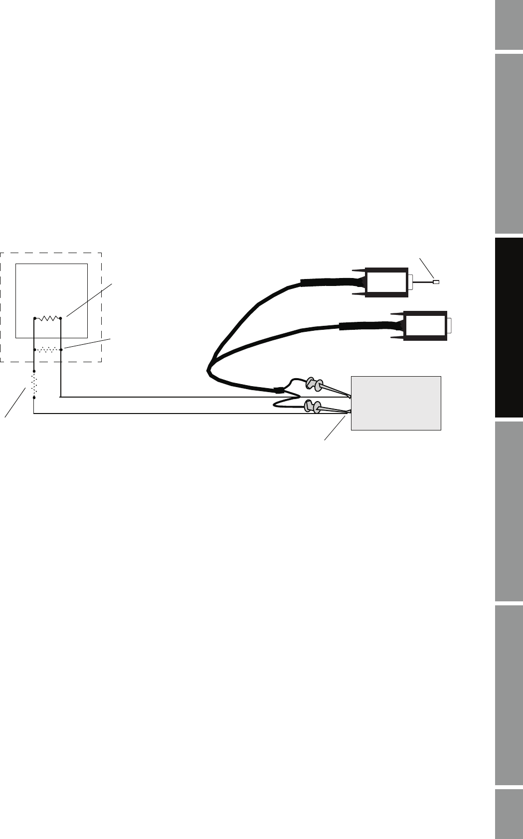
is wired to these terminals. Figure 2-1 shows the wiring for this connection type.
Figure 2-1 HART/Bell 202 temporary or permanent connection to transmitter or multidrop network
1. At the PC, connect the VIATOR HART Interface to the PC’s serial or USB port.
2. Attach the VIATOR HART Interface leads:
• To any point on the network (hard-wired connection)
• Directly to the primary mA output terminals on your transmitter (temporary connection).
See Table 2-6
• To the output wires from the primary mA output terminals on your transmitter (hard-wired
connection). See Table 2-6
The connection is polarity-insensitive; you can attach either lead to either terminal. For
assistance in identifying the primary mA output terminals, see Appendix A.
VIATOR
VIATOR
or
DCS or
PLC
R1
See Step 3
R3
See Step 3
R2
See Step 3
Primary mA output terminals
Tra n sm itt er
USB plug