
Network Router User Manual

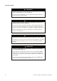
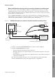
Table Of Contents
- Contents
- Before You Begin
- Installation and Setup
- 2.1 Overview
- 2.2 Installation and setup
- 2.2.1 Ensure required privileges
- 2.2.2 Install the ProLink II software
- 2.2.3 Generate the temporary license
- 2.2.4 Determine your connection type
- 2.2.5 Install the signal converter and connect the wires
- 2.2.6 Configure ProLink II connection parameters and connect to the transmitter
- 2.2.7 Obtain and configure a site key
- 2.3 Troubleshooting the ProLink II installation
- 2.4 Troubleshooting the ProLink II connection
- Using ProLink II Software
- Initial Transmitter Startup Procedures
- Transmitter Configuration, Characterization, and Calibration
- Meter Verification
- Data Logger
- Transmitter Terminal Reference
- Configuring the Discrete Batch Application
- Index
12 ProLink
®
II Software for Micro Motion
®
Transmitters
Installation and Setup
WARNING
On Model 3350/3700 transmitters, opening the wiring compartment in
explosive atmospheres can cause an explosion.
Do not remove the compartment covers in an explosive atmosphere within three
minutes after power is disconnected.
WARNING
On Model 2400S transmitters, removing the transmitter housing cover in a
hazardous area can cause an explosion.
Because the housing cover must be removed to connect to this transmitter using
the service port clips or HART clips, these connections should be used only for
temporary connections, for example, for configuration or troubleshooting purposes.
When the transmitter is in an explosive atmosphere, use a different method to
connect to your transmitter.
WARNING
Removing the core processor lid can expose the operator to electric shock.
To avoid the risk of electric shock, do not touch the power supply wires or terminals
while removing or replacing the core processor lid, or while using the RS-485
terminals.
CAUTION
Connecting a HART device to the transmitter’s primary mA output could
cause transmitter output error.
If the primary mA output is being used for flow control, connecting the VIATOR
HART Interface to the output loop, via either the mA terminals or the HART clips,
could cause the transmitter’s 4–20 mA output to change, which would affect flow
control devices.
Set control devices for manual operation before connecting the VIATOR HART
Interface to the transmitter’s primary mA output loop.