
Network Router User Manual

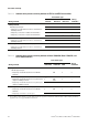
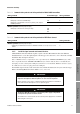
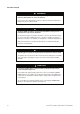
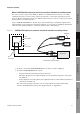
Table Of Contents
- Contents
- Before You Begin
- Installation and Setup
- 2.1 Overview
- 2.2 Installation and setup
- 2.2.1 Ensure required privileges
- 2.2.2 Install the ProLink II software
- 2.2.3 Generate the temporary license
- 2.2.4 Determine your connection type
- 2.2.5 Install the signal converter and connect the wires
- 2.2.6 Configure ProLink II connection parameters and connect to the transmitter
- 2.2.7 Obtain and configure a site key
- 2.3 Troubleshooting the ProLink II installation
- 2.4 Troubleshooting the ProLink II connection
- Using ProLink II Software
- Initial Transmitter Startup Procedures
- Transmitter Configuration, Characterization, and Calibration
- Meter Verification
- Data Logger
- Transmitter Terminal Reference
- Configuring the Discrete Batch Application
- Index

Installation and Use Manual 9
Installation and Setup
ProLink II Setup Transmitter StartupUsing ProLink IIBefore You Begin
2.2.4 Determine your connection type
Different transmitters and networks support different connection types.
• Table 2-2 lists the supported protocols and wiring methods for IFT97xx and RFT97xx
transmitters.
• Table 2-3 lists the supported protocols and wiring methods for Model 1500/2500,
Model 1700/2700, and Series 3000 transmitters.
• Table 2-4 lists the supported protocols and wiring methods for the Model 2400S transmitter.
• Table 2-5 lists the supported protocols and wiring methods for all MVD Direct Connect
systems.
In these tables, and throughout the chapter:
• Temporary – refers to a connection that is not permanent and is typically used only for
configuration and troubleshooting. Because the transmitter housing must be open for the
duration of the connection, these connections should be removed and the housing closed as
soon as possible. The operator should be aware of the safety hazards that result from opening
the transmitter housing.
• Hard-wired – refers to a connection that is made to the permanent wiring, usually a transmitter
output wire or the network that the transmitter is already using. Because hard-wired
connections do not require the transmitter housing to be open, they can be left in place as
desired.
• AN – refers to transmitters with the analog outputs option board
• IS – refers to transmitters with the intrinsically safe outputs option board
• CIO – refers to transmitters with the configurable input/outputs option board
• FF – refers to transmitters with the F
OUNDATION fieldbus input/output option board
• PA – refers to transmitters with the PROFIBUS-PA input/output option board
• DP – refers to transmitters with the PROFIBUS-DP input/output option board
• DN – refers to transmitters with the DeviceNet input/output option board
• MVD Direct Connect – refers to meter installations that include the core processor but do not
include a transmitter. ProLink II is connected directly to the RS-485 terminals on the core
processor or the MVD Direct Connect I.S. barrier.
Once you have determined your connection type, use the Wiring Method # value in the table to direct
you to the correct wiring procedure in Section 2.2.5.