
Network Router User Manual
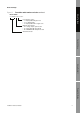

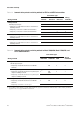
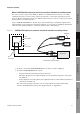
Table Of Contents
- Contents
- Before You Begin
- Installation and Setup
- 2.1 Overview
- 2.2 Installation and setup
- 2.2.1 Ensure required privileges
- 2.2.2 Install the ProLink II software
- 2.2.3 Generate the temporary license
- 2.2.4 Determine your connection type
- 2.2.5 Install the signal converter and connect the wires
- 2.2.6 Configure ProLink II connection parameters and connect to the transmitter
- 2.2.7 Obtain and configure a site key
- 2.3 Troubleshooting the ProLink II installation
- 2.4 Troubleshooting the ProLink II connection
- Using ProLink II Software
- Initial Transmitter Startup Procedures
- Transmitter Configuration, Characterization, and Calibration
- Meter Verification
- Data Logger
- Transmitter Terminal Reference
- Configuring the Discrete Batch Application
- Index

Installation and Use Manual 5
Before You Begin
ProLink II Setup Transmitter StartupUsing ProLink IIBefore You Begin
Figure 1-1 Transmitter model numbers and codes continued
2 4 0 0 S x x x x x x x x x
User interface option:
• 1 = display/LCD with glass lens
• 2 = no display/LCD
• 3 = display/LCD with non-glass lens
Outputs option board:
• A = analog outputs option board
• C = DeviceNet I/O option board
• D = PROFIBUS DP I/O option board
Transmitter model
Model 2400S