
Network Router User Manual


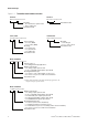
Table Of Contents
- Contents
- Before You Begin
- Installation and Setup
- 2.1 Overview
- 2.2 Installation and setup
- 2.2.1 Ensure required privileges
- 2.2.2 Install the ProLink II software
- 2.2.3 Generate the temporary license
- 2.2.4 Determine your connection type
- 2.2.5 Install the signal converter and connect the wires
- 2.2.6 Configure ProLink II connection parameters and connect to the transmitter
- 2.2.7 Obtain and configure a site key
- 2.3 Troubleshooting the ProLink II installation
- 2.4 Troubleshooting the ProLink II connection
- Using ProLink II Software
- Initial Transmitter Startup Procedures
- Transmitter Configuration, Characterization, and Calibration
- Meter Verification
- Data Logger
- Transmitter Terminal Reference
- Configuring the Discrete Batch Application
- Index

4 ProLink
®
II Software for Micro Motion
®
Transmitters
Before You Begin
Figure 1-1 Transmitter model numbers and codes
R F T 9 7 3 9 x x x x x x x
Mounting:
• R = rack-mount or panel-mount
• D, E = field-mount
Transmitter model
x 7 0 0 x x x x x x x x x x
Outputs option board:
• A = analog outputs option board
• B, C = configurable input/outputs option board
• D = intrinsically safe outputs option board
•E = F
OUNDATION fieldbus outputs option board
• G = PROFIBUS PA outputs option board
Mounting/installation type:
• R = remote (4-wire remote installation)
• I = integral (transmitter mounted on sensor)
• C = transmitter/core processor assembly (9-wire remote installation)
• B = remote core processor with remote transmitter
Transmitter model
3 x x 0 x x x x x x x x x x x x
Sensor interface:
• 0 = none (MVD)
• 5, 6 = 4-wire (MVD)
Mounting:
• R = rack-mount
• P = panel-mount
• A = field-mount
Transmitter model
I F T 9 7 0 x x x x x x x x
Mounting:
•I, M = integral
• R, L, J, S, A = remote
Transmitter model
x 5 0 0 x x x x x x x x x x x x
Software option 1:
• B = Filling and Dosing application
(1)
Outputs option board:
• A = analog outputs option board
• B, C = configurable input/outputs option board
Mounting/installation type:
• D = 4-wire to sensor with integral core processor
• B = remote core processor with remote transmitter
Transmitter model
IFT9701/9703
RFT9739
Model 1700/2700
Model 1500/2500
Series 3000
R F T 9 7 1 2 x x x x x x x
Transmitter model
RFT9712
(1) Model 1500 transmitter with filling and dosing application only.
Requires Outputs option board C.