Instruction Manual P/N 20001909, Rev.
©2006, Micro Motion, Inc. All rights reserved. ELITE, ProLink, and the Micro Motion logo are registered trademarks of Micro Motion, Inc., Boulder, Colorado. MVD and MVD Direct Connect are trademarks of Micro Motion., Inc., Boulder, Colorado. Micro Motion is a registered trade name of Micro Motion, Inc., Boulder, Colorado. The Emerson logo is a trademark of Emerson Electric Co. All other trademarks are property of their respective owners.
Contents Chapter 1 Before You Begin . . . . . . . . . . . . . . . . . . . . . . . . . . . . . . . . . . . . . 1 1.1 1.2 1.3 1.4 1.5 Chapter 2 About this manual . . . . . . . . . . . . . . . . . . . . . . . . . . . . . . . . . . . . . . . . . . . . . . . . . . . . About ProLink II software . . . . . . . . . . . . . . . . . . . . . . . . . . . . . . . . . . . . . . . . . . . . . . 1.2.1 Supported transmitters . . . . . . . . . . . . . . . . . . . . . . . . . . . . . . . . . . . . . . . 1.2.
Contents Chapter 3 Using ProLink II Software . . . . . . . . . . . . . . . . . . . . . . . . . . . . . . 33 3.1 3.2 3.3 3.4 3.5 3.6 3.7 3.8 3.9 3.10 Chapter 4 Overview . . . . . . . . . . . . . . . . . . . . . . . . . . . . . . . . . . . . . . . . . . . . . . . . . . . . . . . . . . Loop tests . . . . . . . . . . . . . . . . . . . . . . . . . . . . . . . . . . . . . . . . . . . . . . . . . . . . . . . . . Trimming the milliamp (mA) output(s) . . . . . . . . . . . . . . . . . . . . . . . . . . . . . .
Contents Chapter 6 Meter Verification . . . . . . . . . . . . . . . . . . . . . . . . . . . . . . . . . . . 67 6.1 6.2 Chapter 7 Overview . . . . . . . . . . . . . . . . . . . . . . . . . . . . . . . . . . . . . . . . . . . . . . . . . . . . . . . . . . Running the meter verification test . . . . . . . . . . . . . . . . . . . . . . . . . . . . . . . . . . . . . . 6.2.1 First panel: Sensor and Transmitter Configuration. . . . . . . . . . . . . . . . . . 6.2.2 Second panel: Test Definition . . . . . . . .
iv ProLink ® II Software for Micro Motion ® Transmitters
1.1 Before You Begin Chapter 1 Before You Begin About this manual This manual explains how to install the Micro Motion® ProLink® II software program, v2.5 and later, on your personal computer (PC). ProLink II Setup This manual also provides an overview of using ProLink II with Micro Motion transmitters. Before using this instruction manual, the reader should be familiar with the Microsoft Windows operating system.
Before You Begin 1.2.2 Uses of ProLink II Using ProLink II, you can: 1.3 • Perform initial transmitter startup procedures • Read process variables • Manage totalizers and inventories • Configure the transmitter • Perform verification and calibration procedures • Read meter status information and alarm conditions • Troubleshoot the meter ProLink II requirements Before starting the ProLink II installation, review the requirements in this section. 1.3.
Before You Begin Table 1-1 ProLink II installation kits Kit contents RS-485 Serial port • Black Box Async RS-232 <-> 2-wire RS-485 Interface Converter (Code IC521A-F) • DB9-DB25 adapter • DB9-DB9 tester • Cable USB • Black Box Async RS-232 <-> 2-wire RS-485 Interface Converter (Code IC521A-F) • Black Box USB-to-serial (RS-232) converter (Code IC138A) • DB9-DB25 adapter • DB9-DB9 tester • Cable Serial port • MACTek VIATOR RS232 HART Interface with integral HART cable terminating in two clips (Model
Before You Begin Figure 1-1 Transmitter model numbers and codes RFT9739 RFT9739xxxxxxx RFT9712 RFT9712xxxxxxx Mounting: • R = rack-mount or panel-mount • D, E = field-mount Transmitter model Transmitter model Series 3000 IFT9701/9703 3xx0xxxxxxxxxxxx IFT970xxxxxxxx Sensor interface: • 0 = none (MVD) • 5, 6 = 4-wire (MVD) Mounting: • R = rack-mount • P = panel-mount • A = field-mount Transmitter model Mounting: • I, M = integral • R, L, J, S, A = remote Transmitter model Model 1500/2500 x500xxxx
Before You Begin Figure 1-1 Transmitter model numbers and codes continued Before You Begin Model 2400S 2400Sxxxxxxxxx User interface option: • 1 = display/LCD with glass lens • 2 = no display/LCD • 3 = display/LCD with non-glass lens Outputs option board: • A = analog outputs option board • C = DeviceNet I/O option board • D = PROFIBUS DP I/O option board Transmitter model ProLink II Setup Using ProLink II Transmitter Startup Installation and Use Manual 5
6 ProLink ® II Software for Micro Motion ® Transmitters
2.1 Before You Begin Chapter 2 Installation and Setup Overview This chapter provides information on installing ProLink II software, connecting to the transmitter, and troubleshooting the installation or connection. To install and set up ProLink II, the following steps are required: 1. Ensure required privileges (see Section 2.2.1) ProLink II Setup 2. Install the ProLink II software onto your PC (see Section 2.2.2) 3. Generate the temporary license (see Section 2.2.3) 4.
Installation and Setup During installation on a Windows NT, Windows 2000, or Windows XP system, if the installer is not in the Administrator group, the installation wizard may display a message warning that the installation may not be successful. If this occurs, the installation wizard will run to completion but the Windows registry may not be updated correctly. If you are subsequently unable to connect to a transmitter, reinstall the software using the required user account. 2.2.
Installation and Setup 2.2.4 Determine your connection type • Table 2-2 lists the supported protocols and wiring methods for IFT97xx and RFT97xx transmitters. • Table 2-3 lists the supported protocols and wiring methods for Model 1500/2500, Model 1700/2700, and Series 3000 transmitters. • Table 2-4 lists the supported protocols and wiring methods for the Model 2400S transmitter. • Table 2-5 lists the supported protocols and wiring methods for all MVD Direct Connect systems.
Installation and Setup Table 2-2 Communication protocols and wiring methods for IFT97xx and RFT97xx transmitters Transmitter type Wiring method IFT9701 IFT9703 RFT9712 RFT9739 Wiring method # ✓ ✓ ✓ 1 ✓ ✓ 2 ✓ 3 ✓ 5 ✓ 6 HART protocol Bell 202 physical layer • Temporary or hard-wired connection to transmitter or multidrop network • Temporary connection to field-mount transmitters • Temporary connection to rack-mount transmitters RS-485 physical layer ✓ • Temporary or hard-wired connection
Installation and Setup Table 2-4 Communication protocols and wiring methods for Model 2400S transmitters Transmitter type Wiring method # • Temporary connection to HART clips AN 8 • Temporary or hard-wired connection to primary mA output or multidrop network AN 1 AN DN DP 7 Before You Begin Wiring method HART protocol (Bell 202 physical layer) Modbus protocol (RS-485 physical layer) • Temporary connection to service port clips Table 2-5 Communication protocols and wiring methods for MVD Dire
Installation and Setup WARNING On Model 3350/3700 transmitters, opening the wiring compartment in explosive atmospheres can cause an explosion. Do not remove the compartment covers in an explosive atmosphere within three minutes after power is disconnected. WARNING On Model 2400S transmitters, removing the transmitter housing cover in a hazardous area can cause an explosion.
Installation and Setup Method 1: HART/Bell 202 temporary or hard-wired connection to transmitter or multidrop network Using a VIATOR HART Interface, the PC can be connected directly to a transmitter’s primary mA output terminals, to the output wires from these terminals, or to any point in a multidrop network that is wired to these terminals. Figure 2-1 shows the wiring for this connection type.
Installation and Setup Table 2-6 Primary mA output terminals – Method 1 Terminals Transmitter PV + PV – RFT9712 17 16 RFT9739 rack-mount Z30 D30 RFT9739 field-mount 17 18 IFT9701/9703 4–20 mA 4–20 mA Model 1500/2500 21 22 Model 1700/2700 AN Model 1700/2700 CIO Model 2400S AN 1 2 Series 3000 panel-mount with screw-type connectors c2 a2 Series 3000 panel-mount with I/O cables 14 15 Series 3000 rack-mount c2 a2 Series 3000 field-mount 2 1 3.
Installation and Setup Method 2: HART/Bell 202 temporary connection to RFT9739 field-mount and RFT9712 transmitters 2. Open the transmitter’s wiring compartment. 3. Locate the Bell 202 hookups inside the wiring compartment and attach the VIATOR HART Interface leads to the prongs (see Figure 2-2). The connection is polarity-insensitive; you can attach either lead to either prong. For assistance in locating the Bell 202 hookups, see Appendix A. Before You Begin 1.
Installation and Setup Method 3: HART/Bell 202 temporary connection to RFT9739 rack-mount transmitters 1. At the PC, connect the VIATOR HART Interface to the PC’s serial or USB port. 2. Attach the leads of a Bell 202 cable to the leads of the VIATOR HART Interface, and insert the cable prongs into the HART jack on the transmitter’s faceplate (see Figure 2-3). The connection is polarity-insensitive; you can insert the cable prongs in either direction. 3.
Installation and Setup Method 4: HART/Bell 202 temporary or hard-wired connection to Model 1700/2700 IS transmitters 1. At the PC, connect the VIATOR HART Interface to the PC’s serial or USB port. 2. Attach the VIATOR HART Interface leads: • To any point on the network (hard-wired connection) • Directly to the primary mA output terminals on your transmitter (temporary connection). See Table 2-8 • To the output wires from the primary mA output terminals on your transmitter (hard-wired connection).
Installation and Setup Figure 2-4 HART/Bell 202 connection to Model 1700/2700 IS transmitters Primary mA output terminals See Step 2 R2 See Step 3 DCS or PLC + Transmitter – External power supply See Step 3 + – R1 See Step 3 VIATOR R3 See Step 3 or VIATOR USB plug Figure 2-5 Model 1700/2700 IS transmitters: Resistance and voltage requirements for HART/Bell 202 connections Rmax = (Vsupply – 12)/0.023 A minimum of 250 ohms and 17.
Installation and Setup Method 5: HART/RS-485 temporary or hard-wired connection to transmitter or multidrop network Using a Black Box signal converter, the PC can be connected directly to a transmitter’s RS-485 terminals, to the output wires from these terminals, or to any point on a multidrop network. Figure 2-6 shows the wiring for this connection type.
Installation and Setup Figure 2-6 HART/RS-485 connection to transmitter or multidrop network RS-485 terminals See Step 4 Transmitter R1 See Step 5 BLACK BOX DCS or PLC 25-pin to 9-pin serial port adapter (if necessary) (not shown) Method 6: Modbus/RS-485 temporary or hard-wired connection to RS-485 multidrop network Note: This method is supported by RFT9739 transmitters, by Model 1500/2500 transmitters, by Model 1700/2700 transmitters with the analog outputs option board, and by Series 3000 transmitt
Installation and Setup Table 2-10 Lead-to-terminal assignments – Method 6 Before You Begin Terminals Transmitter RS-485/A RS-485/B Model 1500/2500 33 34 Model 1700/2700 AN 5 6 Series 3000 panel-mount with screw-type connectors a32 c32 Series 3000 panel-mount with I/O cables 25 24 Series 3000 rack-mount a32 c32 Series 3000 field-mount 12 11 RFT9712 21 22 RFT9739 field-mount 27 26 RFT9739 rack-mount Z22 D22 Note: The Modbus protocol allows only one Modbus master to be active on
Installation and Setup Method 7: Modbus/RS-485 temporary connection to service port Note: This method is supported by all Series 1000, Series 2000 and Series 3000 transmitters. Using a Black Box signal converter, the PC can be connected directly to a transmitter’s service port. Figure 2-8 shows the wiring for this connection type. 1. At the PC, attach the Black Box signal converter to the PC’s serial or USB port, using a 25-pin to 9-pin adapter if necessary. 2.
Installation and Setup Table 2-11 Lead-to-terminal assignments – Method 7 Before You Begin Terminals Transmitter RS-485/A RS-485/B Model 1500/2500 transmitters 33 34 All Model 1700/2700 transmitters 8 7 All Model 2400S transmitters A B Series 3000 panel-mount with screw-type connectors a32 c32 Series 3000 panel-mount with I/O cables 25 24 Series 3000 rack-mount a32 c32 Series 3000 field-mount 12 11 (1) (1) On Model 2400S transmitters, service port connections are made via the serv
Installation and Setup Method 9: Modbus/RS-485 temporary connection to MVD Direct Connect Using a Black Box signal converter, the PC can be connected directly to the RS-485 terminals on the core processor or the MVD Direct Connect I.S. barrier. 1. At the PC, attach the Black Box signal converter to the PC’s serial or USB port, using a 25-pin to 9-pin adapter if necessary. 2. If connecting to the core processor, remove the lid. 3. Connect the signal converter leads to the RS-485 terminals.
Installation and Setup Figure 2-11 Modbus/RS-485 connection to RS-485 terminals on enhanced core processor Core processor Before You Begin RS-485/A RS-485/B 25 to 9 pin serial port adapter (if necessary) ProLink II Setup RS-485 to RS-232 signal converter Figure 2-12 Modbus/RS-485 connection to RS-485 terminals on I.S. barrier RS-485/B RS-485/A Using ProLink II I.S. barrier Non-I.S.
Installation and Setup 2.2.6 Configure ProLink II connection parameters and connect to the transmitter To connect to the transmitter, ProLink II must use connection parameters appropriate to the transmitter. • If you are connecting to an MVD Direct Connect system, ProLink II can use any of the supported communication settings listed in Table 2-13. The core processor auto-detects incoming communications parameters and switches to match.
Installation and Setup Table 2-13 MVD Direct Connect auto-detection limits Option Protocol Modbus RTU (8-bit) Modbus ASCII (7-bit) Baud rate Standard rates between 1200 and 38,400 Parity Even, odd, none Stop bits 1, 2 Before You Begin Parameter Table 2-14 Model 2400S service port auto-detection limits Option Protocol Modbus RTU (8-bit) Modbus ASCII (7-bit) Address Responds to both: • Service port address (111) • Configured Modbus address (default=1) Baud rate Standard rates from 1200 to 38
Installation and Setup Table 2-16 Default communication parameters for RFT97xx and IFT97xx transmitters Default values Transmitter Protocol Baud Data bits(1) Stop bits Parity Address (3) HART 1200 8 1 odd 0 (3) HART 1200 8 1 odd 0 HART 1200 8 1 odd 0 HART 1200 8 1 odd 0 RS-485 HART 1200 8 1 odd 0 Bell 202(3) HART 1200 8 1 odd 0 • Std.
Installation and Setup a. Power down the transmitter. b. Restore power to the transmitter. c. Wait 1–5 seconds. On the Series 3000, wait until the display begins to flash. 6. Click the Connect button. ProLink II will attempt to make the connection. Before You Begin 5. If you are making a service port connection to a Model 1500/2500 transmitter or a Series 3000 transmitter: 7. If an error message appears, see Section 2.4. 2.2.7 Obtain and configure a site key To obtain and configure a site key: 1.
Installation and Setup Figure 2-13 License window c. Enter the site key into the Site Key textbox, then click the Validate button. Note: To minimize the possibility of error, Micro Motion recommends copying and pasting the site key, rather than typing the value. 2.3 Troubleshooting the ProLink II installation If you have problems with the ProLink II installation, review the information in this section and follow the suggestions. If you cannot resolve the problem, contact Micro Motion customer support. 2.
Installation and Setup 2.4 Troubleshooting the ProLink II connection 2.4.1 Before You Begin If you cannot connect to the transmitter, review the information in this section and follow the suggestions. If you cannot resolve the problem, contact Micro Motion customer support. OPC server or OPC client issues If the Context message displays either of the following: The OPC server could not be started. The OPC client database could not be opened.
Installation and Setup 8. Try adding resistance to the connection. • For HART connections, refer to the installation instructions earlier in this chapter. Verify that there is a 250–600 Ω resistor in parallel in the communications circuit. • For HART connections to Model 1700/2700 transmitters with the intrinsically safe outputs option board, ensure that the resistor is in series. Attach the modem across the resistor.
3.1 Before You Begin Chapter 3 Using ProLink II Software Overview This chapter provides information on the ProLink II user interface, including: Starting ProLink II and connecting to a transmitter (see Section 3.3) • The ProLink II help system (see Section 3.4) • Viewing installed options (see Section 3.5) • Viewing process data (see Section 3.6) • Viewing and resetting totalizers and inventories (see Section 3.7) • Viewing status and alarms (see Section 3.
Using ProLink II Software Figure 3-1 ProLink II main window and Connect dialog box 3.3.1 Connecting to a transmitter Depending on your transmitter, you may have several different options for making the connection from ProLink II to the transmitter. Review the following connection guidelines when selecting your connection method. Instructions for making the connection are provided following the guidelines.
Using ProLink II Software • - HART/Bell 202 connections are available on all transmitters that have an mA output, except the Model 1500 with the Filling and Dosing application. The transmitter Model 1500 with the Filling and Dosing application does not support HART communication. - HART/Bell 202 connections use standard connection parameters, so you don’t have to know the transmitter’s configuration.
Using ProLink II Software Polling for devices If you do not know the address of your transmitter: 1. Click the Poll button. ProLink II will poll the network for all Micro Motion transmitters, and display a list of all transmitters found. 2. Select the transmitter to connect to, and click OK. 3.3.2 Disconnecting To disconnect from the currently connected transmitter: 1. Open the Connection menu. 2. Click on the Disconnect option. 3.
Using ProLink II Software 3.6 Viewing process data • Process Variables window • Output Levels window • Totalizer Control window Before You Begin ProLink II provides the following windows for viewing process data and related information: The following windows are available if the associated option has been installed on the transmitter: • API Process Variables window • ED (Enhanced Density) Process Variables window All of these windows are opened from the ProLink menu.
Using ProLink II Software Figure 3-3 3.8 Totalizer Control window Viewing meter status ProLink II allows you to view a variety of status information: • Connection LED – located in the lower right corner of the main window (see Figure 3-1).
Using ProLink II Software • Core Processor Diagnostics window – displays detailed diagnostic data for the core Note: The Core Processor Diagnostics window is always available for viewing. However, the Secure option is required on the ProLink II license in order to make changes and update the device from this window. • 3.
Using ProLink II Software 40 Figure 3-4 Status window Figure 3-5 Alarm Log window ProLink ® II Software for Micro Motion ® Transmitters
Using ProLink II Software 3.9.2 Acknowledging alarms Before You Begin To acknowledge an alarm using ProLink II, you must use the Alarm Log window. You cannot acknowledge alarms from the Status window. To acknowledge an alarm: 1. Open the Alarm Log window. 2. Check the Ack checkbox for each alarm you want to acknowledge. 3.
42 ProLink ® II Software for Micro Motion ® Transmitters
4.1 Before You Begin Chapter 4 Initial Transmitter Startup Procedures Overview The procedures described in this chapter should be performed the first time a transmitter is started. You can use ProLink II, the HART Communicator, AMS software, or the display to perform the procedures: the communications method does not matter.
Initial Transmitter Startup Procedures Figure 4-1 ProLink II loop test options To perform loop tests with ProLink II, see Figure 4-2. If you are testing an mA output, the mA reading does not need to be exact. You will correct differences when you trim the mA output. See Section 4.3.
Initial Transmitter Startup Procedures Figure 4-2 ProLink II – Loop test procedure Before You Begin ProLink Menu Test Fix Milliamp 1 Fix Milliamp 2 Fix Freq Out Enter pulses/second (Hz) value Fix mA Fix Frequency Read output at receiving device Read output at receiving device Correct? Toggle remote input device Read frequency at remote device Fix Discrete Output Verify reading at transmitter Verify reading at transmitter Read output at receiving device Correct? UnFix No output Check out
Initial Transmitter Startup Procedures 4.3 Trimming the milliamp (mA) output(s) Trimming the mA output creates a common measurement range between the transmitter and the device that receives the mA output. For example, a transmitter might send a 4 mA signal that the receiving device reports incorrectly as 3.8 mA. If the transmitter output is trimmed correctly, it will send a signal appropriately compensated to ensure that the receiving device actually indicates a 4 mA signal.
Initial Transmitter Startup Procedures 3. Select Milliamp 1 Trim or Milliamp 2 Trim. The following screen is displayed: Before You Begin Figure 4-4 Milliamp trim wizard – Screen 1 ProLink II Setup This screen allows you to compare the transmitter output (the Present Output value) to the output level being received at an external device. 4. Read the mA output level at the receiving device. 5. Type the value that you read at the receiving device in the Enter Meas box. 6. Click Next.
Initial Transmitter Startup Procedures If the adjusted output is not 4.0: a. Click Back. b. Read the output level at the receiving device and enter the new value in the Enter Meas box. c. Click Next. d. Repeat until the adjusted output is 4.0 (or close enough for your application). If the adjusted output is 4.0, click Next. 7. Click Next to repeat this procedure to trim the 20 mA output. Once you have completed the 20 mA trim, the procedure is complete. Click Finish. 4.
Initial Transmitter Startup Procedures Before You Begin CAUTION If fluid is flowing through the sensor, the sensor zero calibration may be inaccurate, resulting in inaccurate process measurement. To improve the sensor zero calibration and measurement accuracy, ensure that process flow through the sensor has completely stopped. 2. Open the ProLink menu. 3. Click the Calibration option. The calibration options for the currently connected transmitter are displayed (see Figure 4-3). 4.
Initial Transmitter Startup Procedures 8. Wait until the zero time has expired. At the end of this time: • If the Calibration Failure status light turns red, the zero procedure failed. - See your transmitter manual for troubleshooting procedures. - If desired, use the buttons in the dialog box to restore the previous zero value or the zero value established during factory calibration. Note: These two functions are not available on all transmitters.
5.1 Transmitter Configuration Chapter 5 Transmitter Configuration, Characterization, and Calibration Overview This chapter describes: Saving and loading transmitter configuration files • Configuring a transmitter • Using the Gas Unit Configurator utility • Characterizing a transmitter • Calibrating a transmitter for pressure • Calibrating a transmitter for temperature • Configuring pressure compensation • Configuring temperature compensation • Setting up polling Meter Verification 5.
Transmitter Configuration, Characterization, and Calibration CAUTION Editing the configuration file can introduce errors. To avoid introducing errors into the transmitter configuration file, save an original version and work on a copy. If you do this, you will always be able to restore the original version. 5.2.2 Loading a configuration file to a transmitter To load a configuration file: 1. Open the File menu. 2. Click Send to Xmtr from File. 3.
Transmitter Configuration, Characterization, and Calibration ProLink II configuration window Transmitter Configuration Figure 5-1 Meter Verification Data Logger This window is organized into panels. To configure an option: a. Display the appropriate panel by clicking on its tab at the top of the window. b. Set options using standard Windows methods: - Use arrows to display and select from dropdown lists. - Type values into textboxes. - Click on radio buttons to select from a set of options.
Transmitter Configuration, Characterization, and Calibration • To apply the changes and continue with configuration, click Apply. The following popup is displayed: Ensure that your application is in an appropriate state to accept configuration changes, then click OK. The new configuration value(s) will be sent to the transmitter, and will take effect immediately. The tab display color is reset to gray. To avoid immediate reconfiguration, click Cancel.
Transmitter Configuration, Characterization, and Calibration 1. Click the Special Units tab, and click the Gas Unit Configurator button, or open the Tools menu and click Gas Unit Configurator. 2. Select the Time Unit that your special unit will be based on. 3. Click a radio button to specify that your special unit will be defined in terms of English Units or SI Units. 4. Click Next. Transmitter Configuration To use the Gas Unit Configurator: 5. Define the standard density to be used in calculations.
Transmitter Configuration, Characterization, and Calibration Table 5-1 Sensor calibration parameters Sensor type Parameter ProLink II Location T-Series Other K1 Configuration/Density ✓ ✓(1) K2 Configuration/Density ✓ ✓(1) FD Configuration/Density ✓ ✓(1) D1 Configuration/Density ✓ ✓(1) Configuration/Density ✓ ✓(1) Temp coeff (DT) Configuration/Density ✓ ✓(1) Flowcal Configuration/Flow FCF and FT Configuration/Flow ✓(4) FCF Configuration/Flow ✓(5) FTG Configuration/T-Ser
Transmitter Configuration, Characterization, and Calibration Sample calibration tags – All sensors except T-Series Newer tag Transmitter Configuration Figure 5-3 Older tag 19.0005.13 12500142864.44 12502.000 0.0010 14282.000 0.9980 4.44000 310 19.0005.13 12500142864.44 Meter Verification Density calibration factors If your sensor tag does not show a D1 or D2 value: • For D1, enter the Dens A or D1 value from the calibration certificate.
Transmitter Configuration, Characterization, and Calibration To obtain the required value: • For older T-Series sensors, concatenate the FCF value and the FT value from the sensor tag, as shown below. Flow FCF X.XXXX FT X.XX • For newer T-Series sensors, the 10-character string is represented on the sensor tag as the FCF value. The value should be entered exactly as shown, including the decimal points. No concatenation is required.
Transmitter Configuration, Characterization, and Calibration ProLink II calibration options Transmitter Configuration Figure 5-4 Meter Verification 5.5.1 When to calibrate 5.5.2 Data Logger The transmitter is factory calibrated and does not normally need to be calibrated in the field. Calibrate the transmitter only if you must do so to meet regulatory requirements. Micro Motion recommends using meter factors, rather than calibration, to adjust the meter to specific conditions.
Transmitter Configuration, Characterization, and Calibration For T-Series sensors, the optional D3 and D4 calibrations could improve the accuracy of the density measurement. If you choose to perform the D3 and D4 calibration: • Do not perform the D1 or D2 calibration. • Perform D3 calibration if you have one calibrated fluid. • Perform both D3 and D4 calibrations if you have two calibrated fluids (other than air and water). Before beginning density calibration, review the following requirements.
Transmitter Configuration, Characterization, and Calibration D1 and D2 density calibration Close shutoff valve downstream from sensor Fill sensor with D1 fluid Fill sensor with D2 fluid ProLink ProLink Calibration Calibration Density cal - Point 1 Density cal - Point 2 Do Cal Enter density of D2 fluid Do Cal Calibration in Progress Calibration in Progress light turns red light turns red Calibration in Progress Calibration in Progress light turns green light turns green Data Logger Clo
Transmitter Configuration, Characterization, and Calibration Figure 5-6 D3 or D3 and D4 density calibration Close shutoff valve downstream from sensor Fill sensor with D3 fluid Fill sensor with D4 fluid ProLink ProLink Calibration Calibration Density cal - Point 3 Density cal - Point 4 Enter density of D3 fluid Enter density of D4 fluid Do Cal Do Cal Calibration in Progress Calibration in Progress light turns red light turns red Calibration in Progress Calibration in Progress light tur
Transmitter Configuration, Characterization, and Calibration Temperature calibration Transmitter Configuration 5.5.3 Temperature calibration is a two-point procedure: temperature offset calibration and temperature slope calibration. The entire procedure must be completed without interruption. To perform a temperature calibration, see Figure 5-7.
Transmitter Configuration, Characterization, and Calibration 5.6 Compensating for pressure Some Micro Motion transmitters can compensate for the effect of pressure on the sensor flow tubes. Pressure effect is defined as the change in sensor flow and density sensitivity due to process pressure change away from calibration pressure. 5.6.
Transmitter Configuration, Characterization, and Calibration Transmitter Configuration 5. If you will use a static pressure value: a. Type the pressure value in the External Pressure box. b. Click Apply. c. Ensure that neither polled variable is configured to poll for pressure. Polling for temperature is allowed. See Section 5.8. 5.7 Compensating for temperature Temperature data are used in several different calculations. Micro Motion sensors always report temperature data to the transmitter.
Transmitter Configuration, Characterization, and Calibration 5.8 Configuring polling Polling is used to retrieve temperature or pressure data from an external device. These data can then be used for API calculation or other process variable calculations in applications that require pressure or temperature compensation. You may query one or two external devices. You must also ensure that the primary mA output has been wired for HART protocol. See Chapter 2 or the installation manual for your transmitter.
6.1 Transmitter Configuration Chapter 6 Meter Verification Overview Micro Motion recommends that you perform meter verification on a regular basis. Notes: To use meter verification, the transmitter must be paired with an enhanced core processor, and the meter verification option must be installed on your transmitter. To verify that it is installed, use the Installed Options command on the ProLink II View menu.
Meter Verification Figure 6-1 Meter Verification - Sensor and Transmitter Configuration panel ProLink II records the results of previous tests in a meter verification test database stored on the computer on which ProLink II is installed. If you have already run one or more tests on this meter, you can review those previous test results before starting a new test by clicking View Previous Test Results for this Sensor .... This will open the Test Results panel shown in Figure 6-4.
Meter Verification Second panel: Test Definition Transmitter Configuration 6.2.2 The Test Definition panel is shown in Figure 6-2. Figure 6-2 Meter Verification - Test Definition panel Meter Verification Data Logger This panel allows you to enter metadata about each test for auditing purposes. This metadata will be saved with the test results and will also appear on the test report which will be generated at the end of the test. Notes: The metadata fields are optional.
Meter Verification Specification Uncertainty Limit The result of the meter verification test will be a percent uncertainty of normalized tube stiffness. The default limit for this uncertainty is ±4.0%. This limit is stored in the transmitter, and can be changed with ProLink II if necessary by clicking the arrow in the Specification Uncertainty Limit box and selecting a value between 0.1 and 5 %. For most installations, it is advisable to leave the test limits at the default value.
Meter Verification Meter verification is not affected by current process values. However, during the test, process conditions must be stable. To maximize stability: • Maintain a constant temperature and pressure. • Avoid changes to fluid composition (e.g., two-phase flow, settling, etc.). • Maintain a constant flow. For higher test certainty, reduce or stop flow. If stability varies outside test limits, the meter verification procedure will be aborted.
Meter Verification CAUTION Transmitter outputs and process values reported through digital communication will remain fixed at either the configured fault levels or the last measured value for the duration of the test. To ensure the safety of your process: • • Disable all control loops for the duration of the procedure. Ensure that any data reported during this period is handled appropriately. The test takes approximately four minutes to complete.
Meter Verification Fourth panel: Test Results Transmitter Configuration 6.2.4 The Test Results panel, shown in Figure 6-4, summarizes the result of the meter verification test. Figure 6-4 Meter Verification - Test Results panel Meter Verification Data Logger The indicator located at the top of the panel indicates the test result. It is green if the meter passed the test and red if it failed. In addition to the pass/fail indicator, ProLink II shows the changes in tube stiffness on a graph.
Meter Verification You can manipulate the graphed data in various ways by double-clicking the graph to open a configuration dialog or by right-clicking on it to open a contextual menu. From there, you can also export the graph in a number of formats (including “to printer”) by clicking Export. When you have finished reviewing the test results: • To save the data to the ProLink II database, click Next. • To exit without saving, click Cancel.
Meter Verification Transmitter Configuration This report contains all the information supplied in the Test Definition panel, as well as information about the meter's configuration and operating conditions during the test.
76 ProLink ® II Software for Micro Motion ® Transmitters
7.1 Transmitter Configuration Chapter 7 Data Logger Overview The Data Logger tool allows periodic logging of user-selected meter data, including process variables, diagnostic variables, and output levels. Data logged via Data Logger can be viewed or imported into external programs such as spreadsheets for further analysis. Meter Verification 7.2 Using Data Logger The Data Logger screen is shown in Figure 7-1.
Data Logger Note: The log file can become very large if you choose Time Interval and log for a long period of time. Be sure to set the Update Rate accordingly. Figure 7-1 Data Logger 7.2.2 Specifying log contents To specify the types of data to be included in the log: 1. Click on the Process Vars, Diagnostics, Output Vars, or All Vars tab. 2. Double-click on the desired variable in the list, or highlight the variable and click Add. 3.
Data Logger Starting and stopping the logging function You can start and stop Data Logger either manually or automatically. • To start and stop Data Logger manually, use the Start and Stop buttons in the Current Log area of the Data Logger window. • To start Data Logger automatically, enter the date and time in the Start time fields, then check the Enable checkbox. • To stop Data Logger automatically, enter the date and time in the Stop time fields, then check the Enable checkbox.
80 ProLink ® II Software for Micro Motion ® Transmitters
A.1 Transmitter Configuration Appendix A Transmitter Terminal Reference Overview This appendix provides diagrams of the transmitter terminals that can be used for a ProLink II connection.
Transmitter Terminal Reference A.
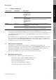
Transmitter Terminal Reference Model 1700/2700 transmitters 2 (–) Transmitter Configuration Figure A-3 1 (+) 5 (RS-485/A) 6 (RS-485/B) 7 Service port (RS-485/B) 8 Service port (RS-485/A) Figure A-4 Meter Verification Note: Terminals 5 and 6 used for communications only by transmitters with the analog outputs option board.
Transmitter Terminal Reference Figure A-5 Model 2400S transmitters with DeviceNet I/O With display Without display 3.
Transmitter Terminal Reference Series 3000 transmitters Series 3000 panel-mount Series 3000 rack-mount Input/output wiring terminals Input/output wiring terminals Label for Model 3300 or 3500 with I/O cables Series 3000 field-mount Input/output wiring terminals Label for Model 3350 or 3700 Meter Verification Card for Model 3300 or 3500 with screw-type or solder-tail terminals Transmitter Configuration Figure A-7 Data Logger Transmitter Terminals Installation and Use Manual 85
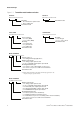
Transmitter Terminal Reference Figure A-8 Core processor Standard 4 (RS-485/B) 3 (RS-485/A) Figure A-9 Enhanced 3 (RS-485/A) 4 (RS-485/B) MVD Direct Connect I.S. barrier 14 (RS-485/B) 13 (RS-485/A) Non-I.S.
B.1 Discrete Batch Appendix B Configuring the Discrete Batch Application About this appendix This appendix explains how to configure the discrete batch application, and provides basic information on batch operation. Note: For more detailed information on operating the discrete batch application, see the Series 3000 MVD transmitter manual. Index Note: The discrete batch application is an optional feature, and may not be installed on your transmitter.
Configuring the Discrete Batch Application Figure B-1 Discrete batch configuration panel 3. Click on the Discrete IO or Discrete Output tab. A panel similar to Figure B-2 is displayed. In this panel: a. Configure the required discrete outputs. - For 1-stage operation, you must configure one discrete output. This output must control either the pump or the primary valve, as appropriate to your application. This discrete output is required.
Configuring the Discrete Batch Application Figure B-2 Discrete IO panel Discrete Batch Index 4. If desired, you can assign a batch control function to a discrete input or discrete event. See Section B.3.4. 5. If you enabled the Batch AOC control option, you should perform batch AOC (automatic overshoot compensation) calibration. Batch AOC is used to minimize the amount of overshoot per batch. See Section B.5. 6. You may optionally configure the batch ticket and ticket printing.
Configuring the Discrete Batch Application Table B-1 Flow sources Flow source Default Description None None • Batch controller is disabled. • START button will not appear on display.
Configuring the Discrete Batch Application Table B-2 Control options continued Discrete Batch Default Description Reset on start No • If set to Yes, the batch totalizer resets when the operator starts the batch. • If set to No, the operator must reset the batch before starting a new batch. Several methods are available for resetting the batch. See Section B.3.4. • If the custody transter application is installed, Reset on start is set to No and cannot be changed.
Configuring the Discrete Batch Application One-stage versus two-stage batching If Number of stages is set to 1, a single pump or valve is used to control the batch. When the batch is started, the pump starts or the valve opens; at the configured target, the pump stops or the valve closes. Open primary, Open secondary, and Close primary values are not required when configuring the preset (see Section B.3.3).
Configuring the Discrete Batch Application Table B-3 Preset parameters continued Default Description Density curves None If an enhanced density variable is selected as the flow source, you must select a density curve that will apply to this preset. The batch total will be based on the density curve for that variable. Overrun(3) 0.0 kg • If Overrun is enabled as a control option, enter the amount over the target value at which batch overrun will be indicated.
Configuring the Discrete Batch Application Example 2 Configure presets by percent of target under the following conditions: • The target is 200 kilograms • The primary valve opens at the start of the batch and closes when 180 kilograms have been delivered • The secondary valve opens when 100 kilograms have been delivered • The end warning occurs when 160 kilograms have been delivered kilograms- = 0.90 Close primary = 180 -----------------------------------200 kilograms Since 0.
Configuring the Discrete Batch Application Figure B-3 Discrete Input Mapping panel Discrete Batch Index Installation and Use Manual 95
Configuring the Discrete Batch Application Table B-4 Batch control assignments Default assignment Function End discrete batch None Inhibit discrete batch Inhibit discrete batch totalizer Assignment options ON state actions Specify the method that will be used to perform the batch control function: • None • Discrete input 1 • Discrete input 2 • Discrete event 1 • Discrete event 2 • Discrete event 3 • Discrete event 4 • Discrete event 5 • Ends the batch. • The batch cannot be resumed.
Configuring the Discrete Batch Application If the batch totalizer is inhibited while a batch is running: And the No-flow timeout batch control option (see Section B.3.2) is set to 0, no timeout alarm will be posted. • And the No-flow timeout batch control option is set to a non-zero value, a timeout alarm will be posted if the timeout period expires before batch totalizing resumes. Discrete Batch B.
Configuring the Discrete Batch Application B.5 Performing Batch AOC calibration Batch AOC (Automatic Overshoot Compensation) keeps the actual quantity delivered as close as possible to the batch target, by minimizing the amount of overshoot. If batch AOC is enabled (see Section B.3.2), batch AOC calibration is required to provide data for the compensation process.
Index C Calibrating 58 AOC 98 how to calibrate for density 59 how to calibrate for temperature 63 when to calibrate 59 zero calibration 48 Characterizing 55 characterization parameters 55 density calibration factors 57 flow calibration values 57 how to characterize 58 when to characterize 55 Communication protocols in installation 9 Configuration configuration file 51 loading to transmitter 52 saving to PC 51 connection parameters 26 discrete batch application batch control methods 94 control options 90 fl
Index G Gas applications normal volume flow as quasi mass flow rate 54 standard volume flow as quasi mass flow rate 54 Gas Unit Configurator tool 54 H HART installing ProLink II for 9 Help 36 I Increment preset 96 Inhibit batch 96 Inhibit totalizer 96 Installation configuring connection parameters 26 connecting the wires 11 connection type 9 HART/Bell 202 temporary connection to Model 2400S transmitters 23 to RFT9712 transmitters 15 to RFT9739 field-mount transmitters 15 to RFT9739 rack-mount transmitters
Index N Normal volume flow as quasi mass flow rate 54 in gas applications 54 O Outputs logging 77 testing 43 trimming the milliamp (mA) output 46 R Registry repairing 30 Reset batch 96 Installation and Use Manual S Sensor, characterizing transmitter for 55 Service port connection 26 Signal converter 2 installing 11 Site key 29 Standard volume flow as quasi mass flow rate 54 in gas applications 54 Start batch 96 Startup loop test 43 milliamp (mA) output trim 46 procedures for transmitter startup 43 zeroin
Index U USB HART Interface troubleshooting 32 USB port troubleshooting 32 Z Zero 48 W Wiring methods 9 HART/Bell 202 temporary connection to Model 2400S transmitters 23 to RFT9712 transmitters 15 to RFT9739 field-mount transmitters 15 to RFT9739 rack-mount transmitters 16 HART/Bell 202 temporary or hard-wired connection to IFT9701/9703 transmitters network 13 to Model 1500/2500 transmitters 13 to Model 1700/2700 transmitters with the analog outputs option board 13 to Model 1700/2700 transmitters with the
©2006, Micro Motion, Inc. All rights reserved. P/N 20001909, Rev. D *20001909* For the latest Micro Motion product specifications, view the PRODUCTS section of our web site at www.micromotion.com Micro Motion Inc.