
Installation Manual

NetSure
™
9500 120kW 400V DC Power System
Installation Manual, IM584001200 (Issue AA, April 14, 2014)
Spec. No: 584001200 Code: IM584001200
Model No: 9500 Issue AA, April 14, 2014
[23 of 25]
8. When you have finished selecting identification numbers
for all rectifiers, repeatedly press
ESC to return to the
Main Menu.
9. Navigate to and select “
Manual” (ENT) / “Rectifier” (ENT)
/ “
All Rect Ctrl” (ENT).
10. Navigate to “Confirm ID/PH”. Press ENT. “Yes”
highlights.
11. Press
ENT to select the operation. Press ENT again to
confirm.
Note:
Check your numbering to be sure it is correct. If there
where conflicts in your numbering, rectifiers with conflicts
will be assigned the next available sequential number.
12. Return to the Main screen by repeatedly pressing
ESC
(escape).
Checking the EPO (Emergency Power Off) Circuit (if
connected)
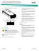
EPO (Emergency Power Off) Function
The Power Module/Bay has an Emergency Power Off (EPO)
function operated by a remote contact provided by the User.
When the EPO switch is momentarily closed, the main AC input
circuit breaker located on the power and control section of the
Power Module/Bay and the battery disconnect circuit breakers (if
connected to the BATT1 CTRL, BATT2 CTRL, BATT3 CTRL, and/or
BATT4 CTRL connectors located on the rear of the power and
control section of the Power Module/Bay) are tripped open to
isolate the system from all electrical sources. Manual intervention
is required to restart the system. Restart the system by first
turning ON the main AC input circuit breaker then the battery
circuit breaker(s).
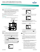
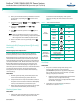
PROCEDURE
1. With the system operating, momentarily depress the
customer furnished Emergency Power Off switch.
2. Verify that the main AC input circuit breaker located on
the power and control section of the Power Module/Bay
and any connected battery circuit breakers open.
3. Restart the system by first turning ON the main AC input
circuit breaker then the battery circuit breaker(s).
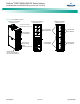
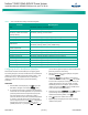
Checking System Status
PROCEDURE
1. Observe the status of the indicators located on the ACU+
controller, rectifier modules, and power and control
section of the Power Module/Bay. If the system is
operating normally, the status of these is as shown in
Table 4.
Table 4. Status and Alarm Indicators
Component Indicator Normal State
ACU+
Controller
Status
(Green)
On
Information
(Yellow)
Off
Warning or
Critical
Alarm
(Red)
Off
Rectifier
Modules
Power
(Green)
On
Protection
(Yellow)
Off
Alarm
(Red)
Off
Power and
Control Section
of Power
Module/Bay
Output Voltage
Present (Green)
On
Control Voltage
Present Indicator (Green)
On
Ground/Insulation Fault
Alarm (Red)
Off
Final Steps
PROCEDURE
1. If any ACU+ Controller configuration settings were
changed, refer to the ACU+ User Instructions
(UM1M820NNB-2) and save a copy of the configuration
file. This file can be used to restore the ACU+ Controller
settings, if required, at a later date.
• Note that provided on a USB drive furnished with the
system is an ACU+ configuration drawing
(C-drawing) and the ACU+ configuration files loaded
into the ACU+ as shipped.
2. Verify there are no external alarms and the local
indicators are as shown in Table 4.