
Installation Manual

NetSure
™
9500 120kW 400V DC Power System
Installation Manual, IM584001200 (Issue AA, April 14, 2014)
Spec. No: 584001200 Code: IM584001200
Model No: 9500 Issue AA, April 14, 2014
[22 of 25]
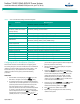
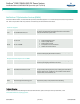
Table 3. ACU+ Controller Basic Settings Local Menu Navigation
Parameter Menu Navigation
Date
Main Menu / Settings / Controller / Date
Time
Main Menu / Settings / Controller / Time
IP Communications Parameters
(IP address, subnet mask address,
gateway address)
Main Menu / Settings / Communication
Float Voltage
Main Menu / Settings / Battery / Charge / Output Voltage
Equalize Voltage
Main Menu / Settings / Battery / Charge / EQ Voltage
Battery Capacity
Main Menu / Settings / Battery / Basic / Ttl Rated Capac
BTRM Feature
Main Menu / Settings / Battery / Basic / BTRM Action
Main Menu / Settings / Battery / Basic / BTRM Voltage
Temperature Compensation
Center Temperature
Main Menu / Settings / Battery / Temp Comp / Temp Comp Ref.
Temperature Compensation Slope
Main Menu / Settings / Battery / Temp Comp / Temp Comp Coeff
Temperature Compensation Sensor
Main Menu / Settings / Battery / Temp Comp / Temp Comp Probe
HVSD Limit
Main Menu / Settings / Rectifier / All Rect Set / HVSD Limit
Rectifier Current Limit
Main Menu / Settings / Rectifier / All Rect Set / Input Current Lmt
Over Voltage Alarm 1
Main Menu / Settings / Power System / Over Voltage 1
Over Voltage Alarm 2
Main Menu / Settings / Power System / Over Voltage 2
Under Voltage Alarm 1
Main Menu / Settings / Power System / Under Voltage 1
Under Voltage Alarm 2
Main Menu / Settings / Power System / Under Voltage 2
Configuring the ACU+ Identification of Rectifiers
When rectifier modules are all installed prior to applying power
and starting the system, the order in which the ACU+ identifies the
rectifiers is by serial number (lowest serial number is Rect 1, next
lowest is Rect 2, etc.). If you prefer the ACU+ to identify the
rectifiers by position in the system, perform the following
procedure.
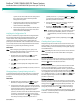
PROCEDURE
1. With the Main screen displayed, press
ENT to go to the
Main Menu. Navigate to and select “
Settings” (ENT).
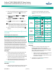
2. If a password screen opens, a password must be entered
to allow the User to make adjustments. If a password was
previously entered and has not yet timed out, skip this
step and proceed to step 3). Otherwise, to enter a
password, with the cursor at the User Name field (default
is “Admin”), press the down arrow key to move cursor
down to the password line. Press
ENT. “0” is highlighted.
Press the up arrow key once to change the “0” to”1”
(default password is “1”), then press
ENT twice. (
Note:
If
you have been assigned a unique User Name and password,
follow this procedure to enter these.)
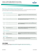
3. With the Settings menu screen displayed, navigate to
and select “
Rectifier” (ENT).
4. Navigate to “
Rect #” (# is used here to represent the
rectifier identification number). Press
ENT. The rectifier
# menu screen is displayed, and the green LED on one
rectifier starts flashing. This is the rectifier currently
identified by the ACU+ as rectifier #. (If this is not the
rectifier you want, press
ESC to return to rectifier menu
screen and select a different rectifier.)
5. Navigate to and select “
Rectifier ID”. Press ENT. Use the
up or down keys to change the ACU+ identification
number for the flashing rectifier. Press
ENT.
6. Press ESC to return to rectifier menu screen.
7. Repeat steps 4) through 6) for each of the remaining
rectifiers in the system.