
Installation Manual

NetSure
™
9500 120kW 400V DC Power System
Installation Manual, IM584001200 (Issue AA, April 14, 2014)
Spec. No: 584001200 Code: IM584001200
Model No: 9500 Issue AA, April 14, 2014
[20 of 25]
ACU+ Controller Initialization
Note:
Your ACU+ controller was programmed with a configuration
file that provides initial settings for all adjustable parameters.
Provided on a USB drive furnished with the system is an ACU+
configuration drawing (C-drawing) and the ACU+
configuration files loaded into the ACU+ as shipped
Refer to the ACU+ Controller Operation Instructions
(UM1M820NNB-2) for detailed instructions.
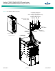
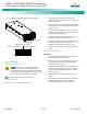
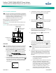
Refer to Figure 18 for locations of the ACU+ local indicators and
navigation keys.
Figure 18. ACU+ Controller Local Indicators and Navigation Keys
PROCEDURE
Note:
The initialization routine takes several minutes. During that
time various alarm indicators may illuminate on the ACU+
front panel and an audible alarm may sound. Disregard all
alarms. An audible alarm can be silenced at any time by
momentarily depressing the
ENT
key on the ACU+ Controller.
1. After the ACU+ is powered on, the display alternates
between the “
Emerson Network Power” screen and a
screen displaying “
Advanced Control Unit Plus Version
***** Starting…”.
2. Next, the language screen appears. Press the up or down
arrow key to select the desired language. Press the
ENT
key to confirm the selection. If no key is pressed within
10 seconds, the ACU+ selects the displayed language
automatically.
3. As initialization continues, the Main screen is displayed,
but with zero volts. Initialization is not complete.
4. When initialization is complete, the Main screen displays
voltage and current normally, and no alarms are active.
5. System information is displayed in multiple screens.
Repetitively press the up or down arrow key to view other
system information screens one by one.
6. From the Main screen, press
ENT to go to the “Main
Menu” screen.
7. From the Main Menu, select a sub-menu by repetitively
pressing the up or down arrow key. The selected sub-
menu will be indicated by the cursor. Press
ENT to open
the sub-menu.
Note:
Repeatedly press the “ESC” key to return in reverse order
level by level from any sub-menu until the Main screen
appears.
8. Verify and set the ACU+ Controller as required for your
application. Refer to the ACU+ Controller Operation
Instructions (UM1M820NNB-2) for procedures. Note
that you will have to program the ACU+ for any of the
following.
a. Battery capacity if different then the factory default
of 120 Ah per battery string for the Emerson
provided Battery Cabinet.
b. Number of battery strings connected to the system.
This is set in the Module 1 Distribution menu.
Depending on the ACU+ configuration installed in
your system (1 battery shunt or 4 battery shunts),
the menu item displayed is “Battery Breaker 1
Installed” or “Battery String 1 Installed”. For a 1-
shunt system, this sets the number of battery
breakers being used in the system. For a 4-shunt
ESC ENT
Menu Navigation Keys
USB Port
10/100M Ethernet
Port (RJ-45)
Status
Indicator
(Green)
Information Alarm
Indicator ( Yellow)
Warning or Critical
Alarm Indicator
(Red)